CAN bus error frames are critical indicators of communication issues within a vehicle’s network. At MERCEDES-DIAGNOSTIC-TOOL.EDU.VN, we provide comprehensive solutions for understanding and interpreting these error frames using DTS Monaco, empowering you to efficiently diagnose and resolve network problems. Explore advanced diagnostics, real-time data analysis, and customized coding to unlock the full potential of your Mercedes-Benz and ensure seamless operation.
Contents
- 1. Understanding the Basics of CAN Bus Error Frames
- 1.1. What is a CAN Bus?
- 1.2. Key Components of a CAN Bus System
- 1.3. What are CAN Bus Error Frames?
- 1.4. Types of CAN Bus Errors
- 1.5. Significance of CAN Bus Error Frames
- 2. Diving Deep: Anatomy of a CAN Bus Error Frame
- 2.1. Structure of a CAN Bus Error Frame
- 2.2. Error Flag Details
- 2.3. Error Delimiter Function
- 2.4. How Error Frames Impact Network Communication
- 2.5. Interpreting Error Frames in Diagnostics
- 3. DTS Monaco: A Powerful Tool for CAN Bus Diagnostics
- 3.1. Overview of DTS Monaco
- 3.2. Key Features of DTS Monaco for CAN Bus Analysis
- 3.3. Setting Up DTS Monaco for CAN Bus Diagnostics
- 3.4. Interpreting CAN Bus Data in DTS Monaco
- 3.5. Practical Examples of Using DTS Monaco
- 4. Interpreting Error Frames in DTS Monaco
- 4.1. Accessing Error Information in DTS Monaco
- 4.2. Common Error Codes and Their Meanings
- 4.3. Using Error Counters for Diagnosis
- 4.4. Filtering and Analyzing Error Frames
- 4.5. Case Studies: Error Frame Interpretation
- 5. Advanced Diagnostics with DTS Monaco
- 5.1. ECU Flashing and Programming
- 5.2. Variant Coding
- 5.3. Diagnostic Services and Routines
- 5.4. Simulating CAN Bus Communication
- 5.5. Automation and Scripting
- 5.6. Practical Applications of Advanced Diagnostics
- 6. Best Practices for CAN Bus Diagnostics
- 6.1. Systematic Approach to Diagnostics
- 6.2. Importance of Accurate Wiring Diagrams
- 6.3. Checking CAN Bus Wiring and Connections
- 6.4. Using a Multimeter for CAN Bus Testing
- 6.5. Preventing Electrical Interference
- 6.6. Documenting Diagnostic Procedures
- 7. Maintaining CAN Bus Integrity
- 7.1. Regular Inspections
- 7.2. Proper Wiring Practices
- 7.3. Using Quality Components
- 7.4. Protecting Against Moisture and Corrosion
- 7.5. Avoiding Overloads
- 7.6. Keeping Software Up-to-Date
- 7.7. Monitoring CAN Bus Performance
- 8. The Future of CAN Bus Diagnostics
- 8.1. Advancements in Diagnostic Tools
- 8.2. The Rise of Remote Diagnostics
- 8.3. Cybersecurity Considerations
- 8.4. The Role of Data Analytics
- 8.5. Integration with Autonomous Systems
- 8.6. The Importance of Continuous Learning
- 9. Frequently Asked Questions (FAQ)
- 9.1. What is the best CAN bus diagnostic tool for Mercedes-Benz vehicles?
- 9.2. How do I open hidden features on my Mercedes-Benz?
- 9.3. How often should I perform maintenance on my Mercedes-Benz?
- 9.4. What are the common causes of CAN bus errors in Mercedes-Benz vehicles?
- 9.5. Can I diagnose CAN bus problems without special tools?
- 9.6. What does a CRC error indicate on the CAN bus?
- 9.7. How do error counters help in CAN bus diagnostics?
- 9.8. What is variant coding, and how is it used in DTS Monaco?
- 9.9. How can I protect my Mercedes-Benz CAN bus system from cyberattacks?
- 9.10. Where can I find reliable wiring diagrams for my Mercedes-Benz?
- 10. Call to Action
1. Understanding the Basics of CAN Bus Error Frames
The Controller Area Network (CAN) bus is the backbone of communication in modern vehicles, enabling various electronic control units (ECUs) to exchange data. Error frames are specific messages transmitted on the CAN bus to signal the detection of an error during data transmission. Understanding these error frames is crucial for diagnosing communication issues within the vehicle’s network.
1.1. What is a CAN Bus?
The CAN bus is a robust communication protocol designed to allow microcontrollers and devices to communicate with each other in applications without a host computer. It is widely used in automotive applications because of its reliability and efficiency.
1.2. Key Components of a CAN Bus System
Understanding the key components of a CAN Bus system helps in effectively diagnosing CAN Bus error frames. Here’s a breakdown of the essentials:
- ECUs (Electronic Control Units): These are the microcontrollers that manage specific functions within the vehicle, such as engine control, braking, and airbag deployment.
- CAN Transceiver: This hardware component translates the data signals between the CAN controller and the physical CAN bus wires.
- CAN Controller: This manages the CAN protocol, handling arbitration, error detection, and message filtering.
- CAN Bus Wires: These are the physical wires that transmit data between ECUs. Typically, a CAN bus uses two wires: CAN High and CAN Low.
- Termination Resistors: These resistors are placed at each end of the CAN bus to prevent signal reflections and maintain signal integrity.
1.3. What are CAN Bus Error Frames?
CAN bus error frames are special messages transmitted over the CAN bus when a node detects an error. These frames do not carry data; instead, they serve as flags indicating a communication fault. The primary purpose of error frames is to alert all other nodes on the network about the presence of an error, prompting them to take appropriate action, such as retransmitting the message.
1.4. Types of CAN Bus Errors
Several types of errors can trigger the transmission of CAN bus error frames:
- Bit Error: Occurs when a node transmitting a bit reads back a different value on the bus.
- Stuff Error: Happens when more than five consecutive bits of the same polarity occur in a message (violating the bit-stuffing rule).
- CRC Error: Detected when the calculated Cyclic Redundancy Check (CRC) value does not match the received CRC value.
- Form Error: Arises when a fixed-form bit field in the CAN frame has an illegal value.
- Acknowledgement Error: Occurs when the transmitter does not receive an acknowledgment from any other node on the network.
1.5. Significance of CAN Bus Error Frames
CAN bus error frames are critical for maintaining the integrity and reliability of communication within a vehicle. By promptly signaling errors, these frames enable ECUs to:
- Detect Communication Faults: Quickly identify issues that could lead to malfunctions.
- Prevent Data Corruption: Ensure that erroneous data is not used for critical operations.
- Trigger Diagnostic Procedures: Initiate troubleshooting processes to resolve the underlying problems.
Understanding CAN bus error frames is essential for anyone involved in automotive diagnostics and repair. At MERCEDES-DIAGNOSTIC-TOOL.EDU.VN, we provide the tools and knowledge necessary to effectively interpret and address these errors, ensuring the optimal performance of your Mercedes-Benz.
2. Diving Deep: Anatomy of a CAN Bus Error Frame
To effectively interpret CAN bus error frames, it is essential to understand their structure and the information they convey. Error frames consist of specific fields that indicate the type and location of the detected error.
2.1. Structure of a CAN Bus Error Frame
A CAN bus error frame comprises two main parts: the Error Flag and the Error Delimiter.
- Error Flag: This field consists of six consecutive bits of the same polarity (either six dominant or six recessive bits). The error flag violates the bit-stuffing rule of CAN, immediately signaling an error condition to all nodes on the bus.
- Error Delimiter: This field consists of eight recessive bits. It provides a separation between the error flag and any subsequent CAN frames, allowing the bus to return to a normal operational state.
2.2. Error Flag Details
The error flag is the primary indicator of an error. Its structure is designed to be easily detectable by all nodes on the CAN bus. The error flag can be in one of two states:
- Active Error Flag: Six consecutive dominant bits. This is transmitted by a node that detects an error while actively transmitting or receiving a message.
- Passive Error Flag: Six consecutive recessive bits. This is transmitted by a node that is in a “passive error” state, meaning it has detected a certain number of errors but is not currently transmitting.
2.3. Error Delimiter Function
The error delimiter is crucial for ensuring that the error frame does not indefinitely disrupt communication on the CAN bus. By providing eight recessive bits, the delimiter allows the bus to transition back to an idle state, enabling subsequent messages to be transmitted.
2.4. How Error Frames Impact Network Communication
When an error frame is transmitted, all other nodes on the CAN bus become aware of the error. This awareness can trigger several responses:
- Retransmission: The transmitting node will typically attempt to retransmit the message, hoping that the error was transient.
- Error Counters: Each node maintains error counters that track the number of transmit and receive errors. If these counters exceed certain thresholds, the node may enter an error passive state or even disconnect from the bus.
- Diagnostic Routines: The detection of frequent error frames can trigger diagnostic routines in the ECUs, prompting them to investigate the cause of the errors.
2.5. Interpreting Error Frames in Diagnostics
Understanding the structure of CAN bus error frames is vital for effective diagnostics. By analyzing the frequency and type of error frames, technicians can gain insights into the nature and location of communication faults. For instance, a high number of CRC errors may indicate issues with data corruption, while frequent acknowledgement errors may suggest problems with a specific ECU’s ability to communicate.
At MERCEDES-DIAGNOSTIC-TOOL.EDU.VN, we offer advanced diagnostic tools and comprehensive training to help you master the interpretation of CAN bus error frames. Our resources enable you to quickly identify and resolve communication issues, ensuring the reliable operation of your Mercedes-Benz. Contact us at +1 (641) 206-8880 for expert assistance.
3. DTS Monaco: A Powerful Tool for CAN Bus Diagnostics
DTS Monaco is a sophisticated diagnostic and engineering tool widely used for Mercedes-Benz vehicles. It provides comprehensive capabilities for analyzing CAN bus communication, interpreting error frames, and performing advanced diagnostics.
3.1. Overview of DTS Monaco
DTS Monaco (Diagnostic Tool Set for Monaco) is a software platform used by automotive engineers and technicians for ECU diagnostics, flashing, and coding. It offers a user-friendly interface and powerful features that enable in-depth analysis of vehicle systems.
3.2. Key Features of DTS Monaco for CAN Bus Analysis
DTS Monaco offers several key features that are particularly useful for CAN bus analysis:
- Real-Time Data Monitoring: Allows you to monitor CAN bus traffic in real-time, viewing message IDs, data payloads, and timestamps.
- Error Frame Detection: Automatically detects and flags error frames, providing immediate notification of communication issues.
- Detailed Error Reporting: Provides detailed information about the type and frequency of error frames, helping you pinpoint the source of the problem.
- ECU Communication: Enables direct communication with ECUs, allowing you to read and write data, perform diagnostic routines, and update software.
- Variant Coding: Allows you to modify ECU parameters and configurations to customize vehicle features.
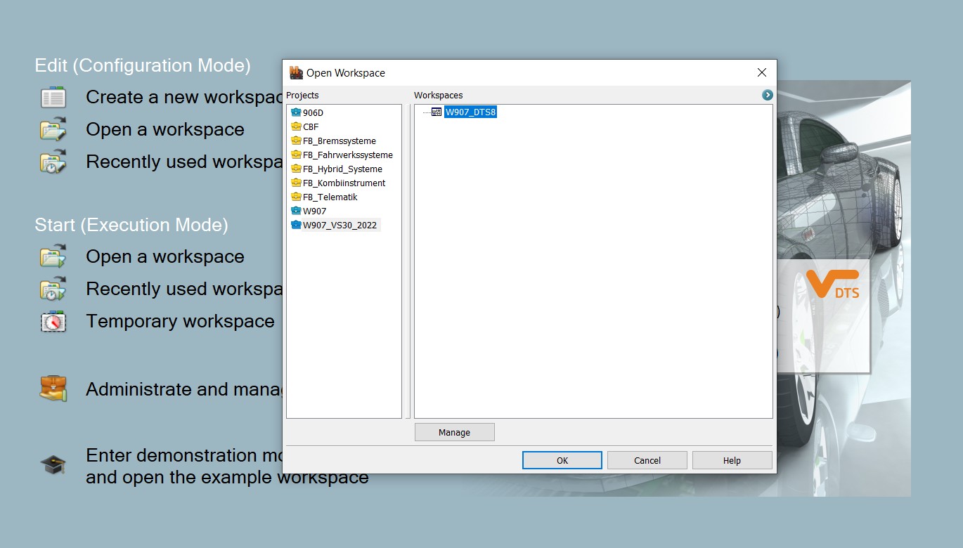
3.3. Setting Up DTS Monaco for CAN Bus Diagnostics
To effectively use DTS Monaco for CAN bus diagnostics, follow these steps:
- Install DTS Monaco: Install the DTS Monaco software on a compatible computer.
- Connect to Vehicle: Connect your computer to the vehicle using a compatible diagnostic interface (e.g., Mercedes-Benz XENTRY Connect).
- Select Project: Open a project that matches your vehicle’s model and year.
- Establish Communication: Establish communication with the relevant ECUs by selecting them from the list of available modules.
- Start Monitoring: Begin monitoring CAN bus traffic using the real-time data monitoring feature.
3.4. Interpreting CAN Bus Data in DTS Monaco
Once you have set up DTS Monaco and are monitoring CAN bus traffic, you can begin interpreting the data:
- Identify Error Frames: Look for error frames in the data stream. DTS Monaco typically highlights these frames to make them easily identifiable.
- Analyze Error Types: Determine the type of error frame (e.g., bit error, CRC error, acknowledgement error) based on the information provided in the error report.
- Correlate with ECU Behavior: Correlate the occurrence of error frames with the behavior of specific ECUs. This can help you identify which ECUs are experiencing communication issues.
- Use Diagnostic Routines: Use DTS Monaco’s diagnostic routines to further investigate the cause of the errors. These routines can perform tests on individual ECUs and provide detailed diagnostic information.
3.5. Practical Examples of Using DTS Monaco
Consider the following practical examples of using DTS Monaco for CAN bus diagnostics:
- Example 1: Intermittent Engine Stalling If a vehicle experiences intermittent engine stalling, you can use DTS Monaco to monitor the engine control unit (ECU) for error frames. If you observe frequent CRC errors, this may indicate a problem with data transmission between the ECU and other modules, such as the fuel pump control module.
- Example 2: ABS Malfunction If the anti-lock braking system (ABS) is malfunctioning, you can use DTS Monaco to monitor the ABS control unit for error frames. If you see frequent acknowledgement errors, this may suggest a problem with the ABS control unit’s ability to communicate with the central gateway module.
With its powerful features and user-friendly interface, DTS Monaco is an indispensable tool for diagnosing CAN bus issues in Mercedes-Benz vehicles. At MERCEDES-DIAGNOSTIC-TOOL.EDU.VN, we provide comprehensive training and support to help you master DTS Monaco and effectively troubleshoot CAN bus problems. Contact us at 789 Oak Avenue, Miami, FL 33101, United States, or Whatsapp: +1 (641) 206-8880 for expert assistance.
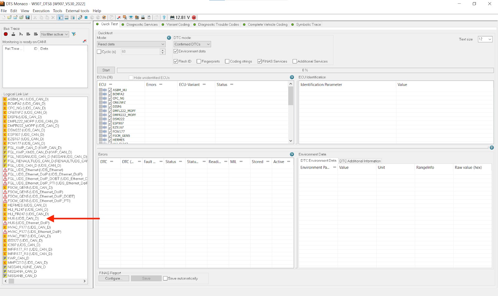
 Error Flags Identification on DTS Monaco
4. Interpreting Error Frames in DTS Monaco
Interpreting error frames in DTS Monaco involves understanding the specific error codes and their implications for the vehicle’s communication network. This process allows technicians to pinpoint the source of the problem and implement effective solutions.
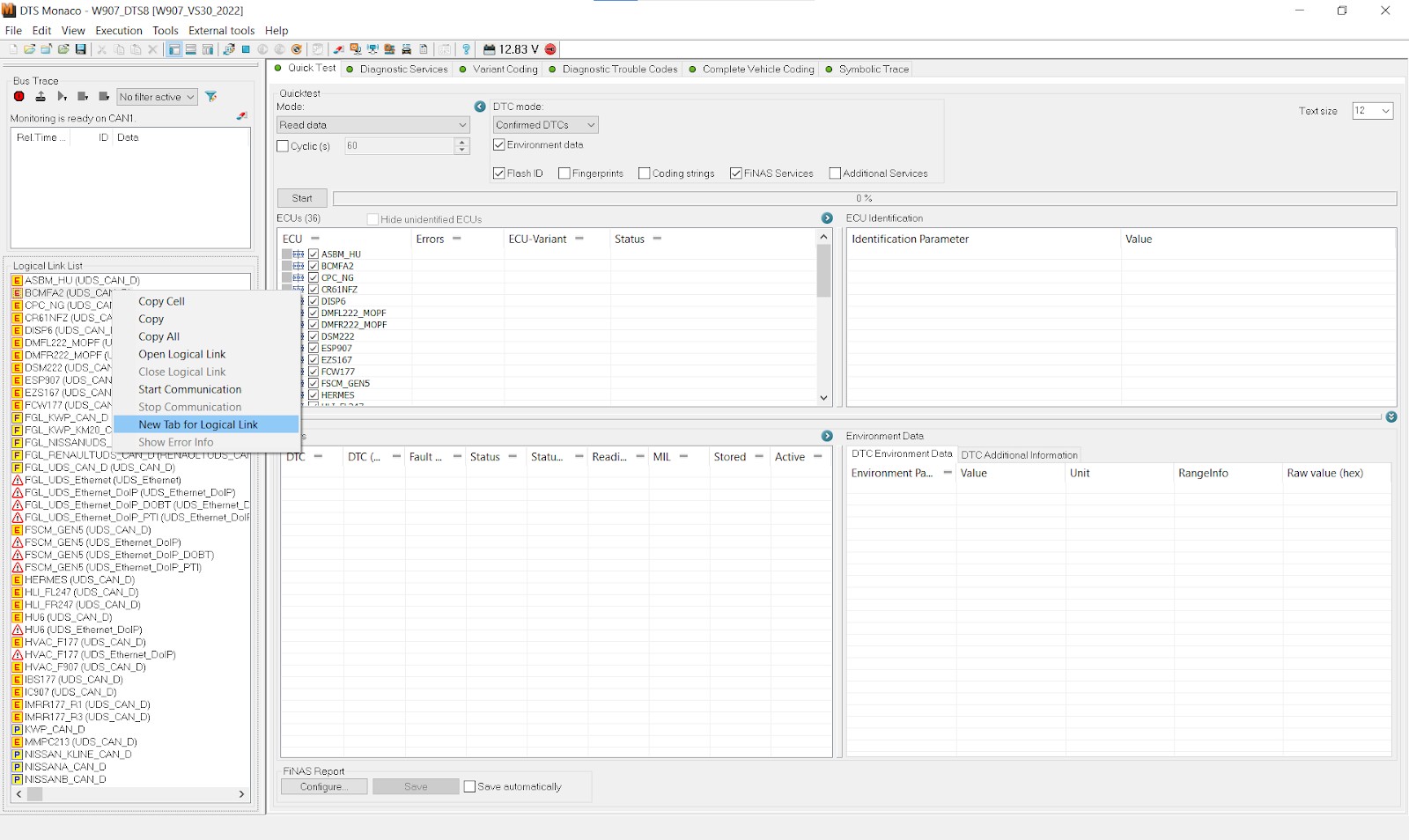
4.1. Accessing Error Information in DTS Monaco
To access error information in DTS Monaco, follow these steps:
- Connect to the Vehicle: Establish a connection between DTS Monaco and the vehicle using a compatible diagnostic interface.
- Select the ECU: Choose the specific ECU you want to analyze from the list of available modules.
- Monitor CAN Bus Traffic: Start monitoring CAN bus traffic to observe real-time data and error frames.
- View Error Details: When an error frame is detected, DTS Monaco will display detailed information about the error, including the error code, timestamp, and affected ECUs.
4.2. Common Error Codes and Their Meanings
Several common error codes can appear in DTS Monaco, each indicating a specific type of communication problem:
- Bit Error: Indicates that a node detected a difference between the bit it transmitted and the bit it read back from the bus. This can be caused by faulty transceivers, wiring issues, or electromagnetic interference.
- Stuff Error: Occurs when more than five consecutive bits of the same polarity are detected in a message, violating the bit-stuffing rule. This typically indicates a problem with the CAN controller or data encoding.
- CRC Error: Signifies that the calculated CRC value does not match the received CRC value, indicating data corruption during transmission. This can be caused by noise, faulty wiring, or ECU malfunctions.
- Form Error: Indicates that a fixed-form bit field in the CAN frame has an illegal value. This is often due to software or firmware issues in the transmitting ECU.
- Acknowledgement Error: Occurs when the transmitting node does not receive an acknowledgement from any other node on the network. This can be caused by a disconnected ECU, wiring problems, or a malfunctioning transceiver.
4.3. Using Error Counters for Diagnosis
DTS Monaco allows you to view error counters for each ECU, providing valuable insights into the frequency and severity of communication issues. Error counters track the number of transmit errors (TEC) and receive errors (REC) for each node on the CAN bus.
- TEC (Transmit Error Counter): Indicates the number of errors detected by a node while transmitting messages.
- REC (Receive Error Counter): Indicates the number of errors detected by a node while receiving messages.
By monitoring these counters, you can identify ECUs that are experiencing a high number of errors, which may indicate underlying problems that need to be addressed.
4.4. Filtering and Analyzing Error Frames
DTS Monaco provides filtering capabilities that allow you to focus on specific types of error frames or messages from particular ECUs. This can be helpful for narrowing down the source of a problem and analyzing the error patterns.
- Filtering by Error Type: You can filter the data stream to show only specific types of error frames, such as CRC errors or acknowledgement errors.
- Filtering by ECU: You can filter the data stream to show only messages from a particular ECU, allowing you to focus on the communication behavior of that module.
4.5. Case Studies: Error Frame Interpretation
Consider the following case studies to illustrate how error frame interpretation can be used for effective diagnostics:
- Case Study 1: Airbag Warning Light A vehicle has an airbag warning light illuminated on the dashboard. Using DTS Monaco, you connect to the airbag control unit and monitor CAN bus traffic. You observe frequent acknowledgement errors from the airbag control unit. This suggests that the airbag control unit is not communicating properly with other modules on the network. Further investigation reveals a loose connection in the wiring harness, which is causing intermittent communication failures.
- Case Study 2: Cruise Control Malfunction A vehicle’s cruise control system is not functioning correctly. Using DTS Monaco, you connect to the engine control unit and monitor CAN bus traffic. You observe a high number of CRC errors associated with messages from the wheel speed sensors. This indicates that the data from the wheel speed sensors is being corrupted during transmission. Further investigation reveals a faulty wheel speed sensor, which is introducing noise into the CAN bus.
Understanding how to interpret error frames in DTS Monaco is essential for effective automotive diagnostics and repair. At MERCEDES-DIAGNOSTIC-TOOL.EDU.VN, we offer expert training and support to help you master these techniques and troubleshoot CAN bus issues efficiently.
 DTS Monaco Interface
5. Advanced Diagnostics with DTS Monaco
DTS Monaco is not just a tool for identifying error frames; it also offers advanced diagnostic capabilities that can help you resolve complex communication issues in Mercedes-Benz vehicles.
5.1. ECU Flashing and Programming
DTS Monaco allows you to flash and program ECUs, which can be necessary for updating software, fixing bugs, or installing new features. Flashing involves replacing the existing software on an ECU with a new version, while programming involves configuring the ECU’s parameters and settings.
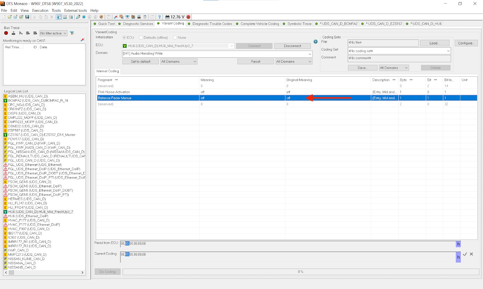
5.2. Variant Coding
Variant coding is a powerful feature of DTS Monaco that allows you to modify ECU parameters and configurations to customize vehicle features. This can be used to enable or disable certain functions, adjust performance settings, or adapt the vehicle to different markets.
5.3. Diagnostic Services and Routines
DTS Monaco provides access to a wide range of diagnostic services and routines that can be used to test individual ECUs and components. These services can perform various tests, such as checking sensor readings, activating actuators, and running self-tests.
5.4. Simulating CAN Bus Communication
DTS Monaco allows you to simulate CAN bus communication, which can be helpful for testing new software or hardware configurations without actually connecting to a vehicle. This feature enables you to create virtual ECUs and simulate their communication behavior, allowing you to identify potential problems before they occur in the real world.
5.5. Automation and Scripting
DTS Monaco supports automation and scripting, allowing you to automate repetitive tasks and create custom diagnostic procedures. This can be particularly useful for performing complex diagnostic routines or testing multiple vehicles.
5.6. Practical Applications of Advanced Diagnostics
Consider the following practical applications of advanced diagnostics with DTS Monaco:
- Retrofitting Features: If you want to retrofit a new feature to a vehicle, such as adaptive cruise control or lane departure warning, you can use DTS Monaco to program the necessary ECUs and configure the vehicle to support the new feature.
- Troubleshooting Complex Issues: If you are facing a complex communication issue that cannot be resolved using standard diagnostic techniques, you can use DTS Monaco’s advanced diagnostic capabilities to analyze the CAN bus traffic, simulate communication scenarios, and identify the root cause of the problem.
- Optimizing Performance: If you want to optimize the performance of a vehicle, you can use DTS Monaco to adjust ECU parameters and settings, such as fuel injection timing, ignition timing, and boost pressure.
By mastering the advanced diagnostic capabilities of DTS Monaco, you can take your automotive diagnostics skills to the next level and effectively troubleshoot even the most challenging communication issues. At MERCEDES-DIAGNOSTIC-TOOL.EDU.VN, we offer comprehensive training and support to help you become proficient in using DTS Monaco for advanced diagnostics. Visit our website at MERCEDES-DIAGNOSTIC-TOOL.EDU.VN for more information.
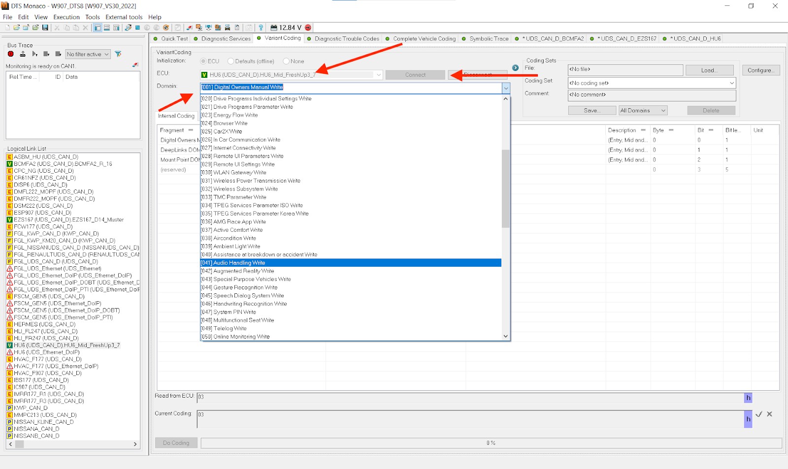 Variant Coding Example
6. Best Practices for CAN Bus Diagnostics
Effective CAN bus diagnostics requires a systematic approach and adherence to best practices. By following these guidelines, you can ensure accurate diagnoses and efficient repairs.
6.1. Systematic Approach to Diagnostics
A systematic approach to CAN bus diagnostics involves the following steps:
- Gather Information: Collect as much information as possible about the problem, including the symptoms, the vehicle’s history, and any recent repairs or modifications.
- Verify the Problem: Confirm that the problem is actually occurring and that it is related to the CAN bus.
- Identify the Affected ECUs: Determine which ECUs are involved in the problem.
- Check for Error Codes: Scan the vehicle’s ECUs for error codes and record any that are found.
- Analyze CAN Bus Traffic: Use DTS Monaco to monitor CAN bus traffic and identify any error frames or other anomalies.
- Perform Diagnostic Tests: Use DTS Monaco’s diagnostic services and routines to test individual ECUs and components.
- Isolate the Problem: Use the information gathered from the previous steps to isolate the root cause of the problem.
- Repair the Problem: Repair or replace any faulty components or wiring.
- Verify the Repair: Confirm that the problem has been resolved and that the CAN bus is functioning properly.
6.2. Importance of Accurate Wiring Diagrams
Accurate wiring diagrams are essential for CAN bus diagnostics. These diagrams show the connections between ECUs and other components, allowing you to trace the CAN bus wiring and identify any potential problems, such as shorts, opens, or loose connections.
6.3. Checking CAN Bus Wiring and Connections
Regularly checking the CAN bus wiring and connections is crucial for preventing communication issues. Inspect the wiring for any signs of damage, such as cuts, abrasions, or corrosion. Check the connections for tightness and ensure that they are free from corrosion.
6.4. Using a Multimeter for CAN Bus Testing
A multimeter can be a valuable tool for CAN bus testing. You can use a multimeter to check the voltage levels on the CAN bus wires, verify the continuity of the wiring, and measure the resistance of the termination resistors.
6.5. Preventing Electrical Interference
Electrical interference can disrupt CAN bus communication and cause error frames. To prevent electrical interference, ensure that the CAN bus wiring is properly shielded and routed away from sources of interference, such as high-voltage wires and electrical motors.
6.6. Documenting Diagnostic Procedures
Documenting your diagnostic procedures is essential for future reference and troubleshooting. Record the steps you took, the results of your tests, and any repairs or modifications you made. This documentation can be helpful if the problem recurs or if you need to troubleshoot similar issues in the future.
By following these best practices, you can improve the accuracy and efficiency of your CAN bus diagnostics and ensure the reliable operation of Mercedes-Benz vehicles. At MERCEDES-DIAGNOSTIC-TOOL.EDU.VN, we provide comprehensive resources and training to help you master these techniques and become a skilled automotive diagnostician. Contact us today at +1 (641) 206-8880 for expert support.
 Checking CAN Bus Wiring
7. Maintaining CAN Bus Integrity
Maintaining the integrity of the CAN bus is essential for ensuring reliable communication and preventing costly repairs. Regular maintenance and proactive measures can help keep your Mercedes-Benz’s CAN bus system in optimal condition.
7.1. Regular Inspections
Regularly inspect the CAN bus wiring and connections for any signs of damage, corrosion, or looseness. Pay close attention to areas that are exposed to moisture, heat, or vibration, as these are more prone to problems.
7.2. Proper Wiring Practices
Ensure that all CAN bus wiring is properly routed, secured, and shielded. Avoid sharp bends, tight constrictions, and contact with sharp edges, as these can damage the wiring and cause communication issues.
7.3. Using Quality Components
When replacing CAN bus components, such as ECUs, transceivers, or wiring, use only high-quality parts that are designed for use in Mercedes-Benz vehicles. Inferior components may not meet the required specifications and can cause communication problems.
7.4. Protecting Against Moisture and Corrosion
Moisture and corrosion can damage CAN bus wiring and connections, leading to communication failures. Protect the wiring and connections from moisture by using waterproof connectors, applying dielectric grease, and sealing any exposed areas.
7.5. Avoiding Overloads
Avoid overloading the CAN bus by adding too many devices or transmitting too much data. Each CAN bus has a limited capacity, and exceeding this capacity can cause communication problems.
7.6. Keeping Software Up-to-Date
Keep the software on all ECUs up-to-date. Software updates often include bug fixes and performance improvements that can help prevent communication issues.
7.7. Monitoring CAN Bus Performance
Regularly monitor the CAN bus performance using DTS Monaco. Keep an eye on the error counters, message latency, and bus utilization. If you notice any unusual patterns or trends, investigate the cause and take corrective action.
By following these maintenance practices, you can help ensure the long-term reliability and integrity of your Mercedes-Benz’s CAN bus system. At MERCEDES-DIAGNOSTIC-TOOL.EDU.VN, we offer a wide range of diagnostic tools, training resources, and expert support to help you maintain your vehicle’s CAN bus system. Contact us today at 789 Oak Avenue, Miami, FL 33101, United States, for assistance.
 CAN Bus Maintenance
8. The Future of CAN Bus Diagnostics
The field of CAN bus diagnostics is constantly evolving, with new technologies and techniques emerging all the time. Staying up-to-date on the latest trends and developments is essential for automotive diagnosticians who want to remain at the forefront of their profession.
8.1. Advancements in Diagnostic Tools
Diagnostic tools are becoming increasingly sophisticated, with new features such as artificial intelligence, machine learning, and cloud connectivity. These advancements are making it easier than ever to diagnose complex CAN bus issues and perform advanced repairs.
8.2. The Rise of Remote Diagnostics
Remote diagnostics is becoming increasingly popular, allowing technicians to diagnose and repair vehicles from a remote location. This can be particularly useful for servicing vehicles in remote areas or for providing support to technicians in the field.
8.3. Cybersecurity Considerations
As vehicles become more connected and autonomous, cybersecurity is becoming an increasingly important consideration. CAN bus systems are vulnerable to cyberattacks, which can compromise vehicle safety and security. Automotive diagnosticians need to be aware of these vulnerabilities and take steps to protect against them.
8.4. The Role of Data Analytics
Data analytics is playing an increasingly important role in CAN bus diagnostics. By analyzing large amounts of data from vehicle CAN bus systems, diagnosticians can identify patterns and trends that can help them predict and prevent future problems.
8.5. Integration with Autonomous Systems
As autonomous driving technology advances, CAN bus systems are becoming increasingly integrated with autonomous systems. This integration requires new diagnostic techniques and tools to ensure the safe and reliable operation of autonomous vehicles.
8.6. The Importance of Continuous Learning
The field of CAN bus diagnostics is constantly evolving, so continuous learning is essential for automotive diagnosticians. Stay up-to-date on the latest trends and developments by attending training courses, reading industry publications, and participating in online forums.
By embracing these trends and continuously expanding their knowledge, automotive diagnosticians can remain at the forefront of their profession and provide the highest level of service to their customers. At MERCEDES-DIAGNOSTIC-TOOL.EDU.VN, we are committed to providing the latest diagnostic tools, training resources, and expert support to help you succeed in the ever-evolving world of automotive diagnostics.
9. Frequently Asked Questions (FAQ)
9.1. What is the best CAN bus diagnostic tool for Mercedes-Benz vehicles?
The best CAN bus diagnostic tool for Mercedes-Benz vehicles is DTS Monaco, due to its comprehensive features and compatibility with Mercedes-Benz systems.
9.2. How do I open hidden features on my Mercedes-Benz?
You can open hidden features on your Mercedes-Benz using DTS Monaco by modifying ECU parameters through variant coding.
9.3. How often should I perform maintenance on my Mercedes-Benz?
You should perform maintenance on your Mercedes-Benz according to the manufacturer’s recommendations, typically every 10,000 miles or once a year.
9.4. What are the common causes of CAN bus errors in Mercedes-Benz vehicles?
Common causes of CAN bus errors include wiring issues, faulty ECUs, electrical interference, and software problems.
9.5. Can I diagnose CAN bus problems without special tools?
While some basic checks can be done without special tools, diagnosing CAN bus problems effectively requires diagnostic tools like DTS Monaco.
9.6. What does a CRC error indicate on the CAN bus?
A CRC error indicates data corruption during transmission, possibly due to noise or faulty wiring.
9.7. How do error counters help in CAN bus diagnostics?
Error counters help identify ECUs experiencing a high number of errors, indicating potential underlying issues.
9.8. What is variant coding, and how is it used in DTS Monaco?
Variant coding is modifying ECU parameters to customize vehicle features, done through DTS Monaco’s coding functions.
9.9. How can I protect my Mercedes-Benz CAN bus system from cyberattacks?
Protect your CAN bus system by keeping software up-to-date and being aware of potential vulnerabilities.
9.10. Where can I find reliable wiring diagrams for my Mercedes-Benz?
Reliable wiring diagrams can be found in Mercedes-Benz service manuals or through authorized service providers.
10. Call to Action
Ready to take control of your Mercedes-Benz diagnostics? At MERCEDES-DIAGNOSTIC-TOOL.EDU.VN, we provide the tools and expertise you need to master CAN bus diagnostics and unlock the full potential of your vehicle.
- Get Expert Guidance: Our team of experienced technicians is available to answer your questions and provide personalized support.
- Access Comprehensive Training: We offer a range of training resources, including online courses, workshops, and tutorials, to help you master DTS Monaco and other diagnostic tools.
- Find the Right Tools: We carry a wide selection of diagnostic tools and equipment, including DTS Monaco interfaces, CAN bus analyzers, and wiring diagrams.
Don’t let CAN bus issues keep you off the road. Contact us today at 789 Oak Avenue, Miami, FL 33101, United States, or Whatsapp: +1 (641) 206-8880, or visit our website at MERCEDES-DIAGNOSTIC-TOOL.EDU.VN to learn more about our products and services. Let us help you keep your Mercedes-Benz running smoothly and reliably.