During vehicle development and testing, handling Diagnostic Trouble Codes (DTCs) involves cyclical monitoring, event debouncing, and standardized data exchange, all crucial for pinpointing malfunctions; MERCEDES-DIAGNOSTIC-TOOL.EDU.VN provides detailed resources and tools to navigate these processes effectively. Understanding these procedures ensures efficient troubleshooting and optimal vehicle performance. Let’s examine DTC handling, common exchange formats, and troubleshooting.
Contents
- 1. Understanding DTC Handling in Vehicle Development
- 1.1. Cyclical Monitoring by Application Software
- 1.2. Event Debouncing to Avoid False Positives
- 1.3. Standardized Data Exchange Formats (DEXT, ODX)
- 1.4. Case Studies and Examples
- 1.5. Utilizing MERCEDES-DIAGNOSTIC-TOOL.EDU.VN for DTC Handling
- 2. Exploring Common Exchange Formats for DTCs
- 2.1. Understanding DEXT Format in AUTOSAR
- 2.2. Understanding ODX Format in ASAM
- 2.3. Comparing DEXT and ODX
- 2.4. The Importance of a Single Source of Truth
- 2.5. Leveraging MERCEDES-DIAGNOSTIC-TOOL.EDU.VN for Understanding Exchange Formats
- 3. Delving into the DTC in the Control Unit
- 3.1. Application Software with Diagnostic Functions (Monitor)
- 3.2. Diagnostic Events: Linking Monitors to DTCs
- 3.3. Debouncing of the Events: Preventing False Alarms
- 3.4. Function Deactivation: Implementing FMEA in the Control Unit
- 3.5. Utilizing MERCEDES-DIAGNOSTIC-TOOL.EDU.VN for Control Unit DTC Management
- 4. Examining the Operation-Cycle in DTC Management
- 4.1. Defining the Operation-Cycle
- 4.2. Dynamic Status of DTCs (ISO 14229-1:2013)
- 4.3. Example of Dynamic DTC Behavior
- 4.4. Implications for Diagnostic Strategies
- 4.5. Utilizing MERCEDES-DIAGNOSTIC-TOOL.EDU.VN for Operation Cycle Insights
- 5. Exploring Error Memory: DTC Snapshot and Extended Data
- 5.1. DTC Snapshot Data (Freeze Frames)
- 5.2. Details of Snapshot Data Structure
- 5.3. Extended Data
- 5.4. Structure of Extended Data Block
- 5.5. Utilizing MERCEDES-DIAGNOSTIC-TOOL.EDU.VN for Error Memory Analysis
- 6. Further DTC Relevant Information: Severity, Debouncing, and Function Inhibit
- 6.1. Severity
- 6.2. Debouncing
- 6.3. Malfunction Indicator
- 6.4. Function Inhibit
- 6.5. Utilizing MERCEDES-DIAGNOSTIC-TOOL.EDU.VN for Comprehensive DTC Understanding
- 7. The Diagnostic Communication Manager (DCM) in DTC Handling
- 7.1. Encoding and Transmission of DTC Data
- 7.2. UDS Service 0x19 (ReadDTC)
- 7.3. Ensuring Identical Coding and Decoding
- 7.4. Challenges for the Diagnostic Tester
- 7.5. Utilizing MERCEDES-DIAGNOSTIC-TOOL.EDU.VN for DCM Insights
- 8. The DTC in the Diagnose Tester (ODX)
1. Understanding DTC Handling in Vehicle Development
How are Diagnostic Trouble Codes (DTCs) handled during the vehicle development and testing phases? Diagnostic Trouble Codes (DTCs) are handled through systematic monitoring, debouncing, and standardized data exchange to ensure effective fault detection and analysis. This involves cyclical monitoring by application software, debouncing of events to prevent false positives, and using standardized formats like DEXT and ODX for data exchange between ECUs and diagnostic tools.
During vehicle development, DTCs are integral to identifying, addressing, and mitigating potential issues. This section delves into the meticulous processes involved in handling DTCs, focusing on cyclical monitoring, event debouncing, and the significance of standardized data exchange formats.
1.1. Cyclical Monitoring by Application Software
How does cyclical monitoring work in detecting DTCs? Application software employs cyclical monitoring to continually assess signals against predefined limits, ensuring early detection of any deviations indicative of potential faults, enhancing overall vehicle reliability.
Application software, equipped with diagnostic functions known as monitors, plays a crucial role in the early detection of DTCs. These monitors constantly assess signals against predefined limit values. Compliance or non-compliance with these values is communicated to the Diagnostic Manager (DM) in the form of events. This proactive approach ensures that potential issues are identified early, often before they escalate into significant problems.
For example, consider a battery monitoring system. The application software continuously checks the battery voltage and signals any deviations outside acceptable limits (e.g., 11.2 V and 15.2 V in Figure 2 of the original article) to the Diagnostic Manager. The exact monitoring function with its limit values remains proprietary, but the events triggered by the application are defined in a standardized format like DEXT, facilitating efficient communication across different systems.
1.2. Event Debouncing to Avoid False Positives
Why is event debouncing essential in DTC handling? Event debouncing is essential to prevent false DTC triggers from transient issues, ensuring diagnostic accuracy and avoiding unnecessary fault reactions.
Not every minor or transient fault should immediately trigger a DTC. Event debouncing is a crucial step to filter out such false positives. This involves employing time-based, counter-based, or internal debouncing strategies to confirm the persistence of a fault before generating a DTC.
-
Time-based Debouncing: An error must be present for a certain duration to become effective as a confirmed DTC.
-
Counter-based Debouncing: An error counter increments or decrements based on the fault’s persistence, providing a granular approach to debouncing.
-
Internal Debouncing: The monitor delivers already debounced events, managed internally without involving the DM.
By implementing these strategies, vehicle manufacturers can ensure that only genuine, persistent issues are flagged, reducing unnecessary diagnostics and repairs.
1.3. Standardized Data Exchange Formats (DEXT, ODX)
What role do DEXT and ODX formats play in DTC handling? DEXT and ODX formats standardize data exchange between ECUs and diagnostic tools, ensuring consistency and efficient communication for accurate diagnostics and troubleshooting.
Standardized data exchange formats like DEXT (in AUTOSAR) and ODX (in ASAM) are essential for seamless communication between ECUs and diagnostic tools. These formats facilitate the exchange of DTC-related information, including event details, snapshot data, and extended data.
-
DEXT: Used primarily in embedded electronics development within the AUTOSAR framework.
-
ODX: Used for off-board diagnostics, ensuring that diagnostic tools can accurately interpret data from various ECUs.
These formats ensure that all relevant data is consistently interpreted, regardless of the ECU manufacturer or diagnostic tool used, streamlining the diagnostic process and reducing the risk of misinterpretation.
1.4. Case Studies and Examples
Can you provide examples of how DTCs are handled during vehicle development? Real-world examples illustrate DTC handling during vehicle development through cyclical monitoring, debouncing strategies, and standardized data formats, enhancing diagnostic accuracy and efficiency.
Consider a scenario where the Engine Control Unit (ECU) detects a misfire in one of the cylinders. The application software monitors the engine’s performance and identifies the misfire event. To prevent a false positive, the ECU employs a counter-based debouncing strategy. If the misfire persists for a specific number of engine cycles, the ECU confirms the fault and generates a DTC. This DTC, along with relevant snapshot data (e.g., engine speed, temperature, and load), is then stored in the error memory. A technician can retrieve this information using a diagnostic tool that communicates with the ECU via the ODX format.
Another example involves the Anti-lock Braking System (ABS). If the ABS detects a fault in one of the wheel speed sensors, it triggers an event. The DM uses a time-based debouncing strategy to ensure that the fault is not due to a transient issue. If the fault persists for a certain period, the DM confirms the DTC and activates the Function Inhibition Manager (FIM) to disable certain ABS functions to ensure safety.
1.5. Utilizing MERCEDES-DIAGNOSTIC-TOOL.EDU.VN for DTC Handling
How can MERCEDES-DIAGNOSTIC-TOOL.EDU.VN assist in DTC handling? MERCEDES-DIAGNOSTIC-TOOL.EDU.VN provides tools, resources, and expert guidance for effective DTC handling, ensuring accurate diagnostics and optimized vehicle maintenance.
MERCEDES-DIAGNOSTIC-TOOL.EDU.VN offers comprehensive resources and tools for effectively handling DTCs during vehicle development and testing. This includes detailed guides on using diagnostic tools, understanding standardized data formats, and implementing debouncing strategies.
-
Diagnostic Tools: Provides information on various diagnostic tools suitable for Mercedes-Benz vehicles.
-
Data Formats: Explains the intricacies of DEXT and ODX formats.
-
Debouncing Strategies: Offers insights into implementing effective debouncing techniques.
By leveraging these resources, technicians and engineers can enhance their ability to accurately diagnose and resolve issues, ensuring optimal vehicle performance.
 DTC Snapshot Data
Figure 4: Details of DTC Snapshot Data (FreezeFrames)
2. Exploring Common Exchange Formats for DTCs
What are the common exchange formats used for DTCs, and how do they improve vehicle diagnostics? Common exchange formats like DEXT and ODX standardize DTC data, ensuring seamless communication between ECUs and diagnostic tools, leading to more accurate and efficient vehicle diagnostics.
The exchange of DTC data between ECUs and diagnostic tools requires standardized formats to ensure consistency and accuracy. This section explores the common exchange formats used for DTCs, focusing on DEXT (in AUTOSAR) and ODX (in ASAM), and their role in improving vehicle diagnostics.
2.1. Understanding DEXT Format in AUTOSAR
How does the DEXT format function within the AUTOSAR framework for DTC exchange? The DEXT format in AUTOSAR facilitates standardized DTC data exchange, ensuring consistent interpretation and efficient communication between ECUs and diagnostic tools for improved diagnostics.
DEXT (Diagnostic Exchange Format) is an exchange format used within the AUTOSAR (Automotive Open System Architecture) framework for embedded electronics development. It defines the structure and content of diagnostic data, including DTCs, events, and associated parameters.
Key aspects of the DEXT format include:
-
Event Definition: Defining events triggered by monitors in the application software.
-
DTC Assignment: Linking events to specific DTCs.
-
Debouncing Configuration: Specifying debouncing strategies for events.
-
Data Structure: Defining the structure of snapshot data and extended data.
By standardizing these aspects, DEXT ensures that diagnostic data is consistently interpreted across different ECUs and diagnostic tools, streamlining the diagnostic process.
2.2. Understanding ODX Format in ASAM
What is the role of the ODX format in off-board diagnostics, and how does it relate to DTCs? The ODX format in ASAM standardizes off-board diagnostic data, ensuring diagnostic tools accurately interpret ECU data for effective troubleshooting.
ODX (Open Diagnostic data eXchange) is an exchange format used for off-board diagnostics, standardized by ASAM (Association for Standardization of Automation and Measuring Systems). It provides a standardized way to describe diagnostic data, including DTCs, freeze frames, and extended data, for diagnostic tools.
Key features of the ODX format include:
-
Vehicle Information: Describing vehicle-specific information, such as the VehicleInformationTable (VIT).
-
ECU Software Versions: Identifying the exact software versions of ECUs installed in the vehicle.
-
Data Interpretation: Providing the necessary interpretation for various software variants.
-
Additional Data: Including audience, speech information, and meta-information.
ODX ensures that diagnostic tools can accurately interpret data from various ECUs, regardless of the vehicle manufacturer or software version, facilitating efficient troubleshooting and repair.
2.3. Comparing DEXT and ODX
How do DEXT and ODX compare in terms of functionality and application in DTC handling? DEXT focuses on in-vehicle communication within AUTOSAR, while ODX standardizes off-board diagnostics, both ensuring consistent data interpretation for effective DTC handling.
While both DEXT and ODX serve the purpose of standardizing diagnostic data, they have different scopes and applications.
| Feature | DEXT | ODX |
|---|---|---|
| Scope | Embedded electronics development | Off-board diagnostics |
| Framework | AUTOSAR | ASAM |
| Data Included | Events, DTC assignments, debouncing config | Vehicle information, ECU software versions |
| Additional Data | Severity, malfunction indicator, function inhibit | Audience, speech information, meta-information |
| Primary Application | In-vehicle communication | Diagnostic tool communication |
DEXT focuses on standardizing data within the vehicle’s electronic control units (ECUs), while ODX standardizes data for communication between the vehicle and external diagnostic tools.
2.4. The Importance of a Single Source of Truth
Why is a “Single Source of Truth” essential for managing DTC-related data? A “Single Source of Truth” ensures consistency and accuracy in DTC-related data across all systems, reducing redundancy and preventing contradictions for reliable diagnostics.
To ensure consistency and accuracy, it is essential to have a “Single Source of Truth” for DTC-related data. This involves combining all relevant information from DEXT and ODX into a common database. This approach ensures that:
-
ODX and DEXT files always contain the same information.
-
Data is consistent and free of contradictions.
-
Software developers can focus on the technical characteristics of DTCs without needing to know format details.
-
Diagnostic developers can add diagnosis-relevant metadata (texts, variants, etc.).
By using a common database, the necessary ODX and DEXT files can be generated consistently and without redundancy, streamlining the diagnostic process.
2.5. Leveraging MERCEDES-DIAGNOSTIC-TOOL.EDU.VN for Understanding Exchange Formats
How can MERCEDES-DIAGNOSTIC-TOOL.EDU.VN help in understanding and utilizing DEXT and ODX formats? MERCEDES-DIAGNOSTIC-TOOL.EDU.VN offers detailed resources and expert guidance on DEXT and ODX formats, ensuring accurate diagnostics and optimized vehicle maintenance.
MERCEDES-DIAGNOSTIC-TOOL.EDU.VN provides extensive resources and expert guidance for understanding and utilizing DEXT and ODX formats. This includes detailed explanations of the formats, practical examples of their application, and tools for converting between them.
-
Format Explanations: Comprehensive explanations of DEXT and ODX formats.
-
Practical Examples: Real-world examples of how these formats are used in vehicle diagnostics.
-
Conversion Tools: Tools for converting between DEXT and ODX formats.
By leveraging these resources, technicians and engineers can enhance their understanding of these formats and improve their ability to accurately diagnose and resolve issues.
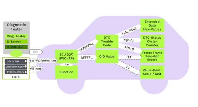 DTCs and associated data objects
Figure 6: DTCs and associated data objects
3. Delving into the DTC in the Control Unit
How do DTCs function within the control unit of a vehicle? DTCs in a control unit involve application software monitoring, diagnostic events, event debouncing, and function deactivation to manage and respond to detected faults.
The journey of a DTC from detection in an electronic control unit (ECU) to diagnosis in the workshop involves several key steps. This section delves into the details of how DTCs function within the control unit, focusing on application software with diagnostic functions, diagnostic events, event debouncing, and function deactivation.
3.1. Application Software with Diagnostic Functions (Monitor)
What role does application software play in monitoring and detecting DTCs within a control unit? Application software continuously monitors signals and events against predefined limits, ensuring early detection and reporting of potential faults in the control unit.
Application software, equipped with diagnostic functions known as monitors, plays a crucial role in detecting DTCs within the control unit. These monitors cyclically monitor signals for compliance with relevant limit values. Compliance or non-compliance with these limit values is signaled to the Diagnostic Manager (DM) in the form of events.
Key functions of the application software include:
-
Signal Monitoring: Continuously monitoring signals against predefined limits.
-
Event Signaling: Signaling compliance or non-compliance to the DM.
-
Data Provision: Providing relevant data for snapshot data and extended data.
By continuously monitoring signals and events, the application software ensures early detection of potential faults, enabling timely intervention and preventing escalation.
3.2. Diagnostic Events: Linking Monitors to DTCs
How are diagnostic events linked to specific DTCs, and why is this important for error management? Diagnostic events are linked to specific DTCs to ensure accurate fault identification and reporting, enabling effective troubleshooting and maintenance.
The events triggered by the monitors in the application software are assigned to specific DTCs. These DTCs are primarily intended for the Aftersales Service and depend on the respective diagnostic strategy. Typically, the OEM determines the DTC to be used uniformly for its vehicles.
Key aspects of linking diagnostic events to DTCs include:
-
Event Assignment: Assigning events of the monitors to specific DTCs.
-
Standardization: Ensuring uniform DTC usage across vehicles.
-
Error Reporting: Providing a standardized way to report errors to the Aftersales Service.
Several events can be assigned to the same DTC, or different events can be assigned to different DTCs, depending on the diagnostic strategy.
3.3. Debouncing of the Events: Preventing False Alarms
Why is debouncing of events necessary in DTC handling within the control unit? Debouncing of events prevents false DTC triggers from transient issues, ensuring accurate fault detection and avoiding unnecessary diagnostic procedures.
Not every small fault should immediately generate a DTC and trigger the associated fault reaction. Debouncing is crucial to filter out false positives. Most events are debounced using time-based, counter-based, or internal debouncing strategies.
-
Time-based Debouncing: An error must be present for a certain time to become effective as a DTC.
-
Counter-based Debouncing: An error counter is incremented or decremented based on the fault’s persistence.
-
Internal Debouncing: The monitor delivers already debounced events, managed internally without involving the DM.
By implementing these strategies, the control unit ensures that only genuine, persistent issues are flagged, reducing unnecessary diagnostics and repairs.
3.4. Function Deactivation: Implementing FMEA in the Control Unit
How does function deactivation, or FIM, implement FMEA within the control unit in response to DTCs? Function deactivation, or FIM, implements FMEA by deactivating specific vehicle functions in response to DTCs, mitigating potential risks and ensuring safety.
If a DTC is stored as confirmed, the vehicle must react appropriately to this error. The vehicle manufacturer analyzes such faults and their effects during the development of the vehicle. This is typically described with the aid of an FMEA (Failure Mode and Effects Analysis), and the corresponding reactions of the vehicle are determined. The FIM ultimately implements the parts of the FMEA in the control unit.
Key aspects of function deactivation include:
-
FMEA Analysis: Analyzing faults and their effects during vehicle development.
-
Vehicle Reaction: Determining appropriate reactions to confirmed DTCs.
-
FIM Implementation: Implementing FMEA findings in the control unit.
By deactivating certain functions in response to DTCs, the FIM ensures that the vehicle operates safely and minimizes the risk of further damage.
3.5. Utilizing MERCEDES-DIAGNOSTIC-TOOL.EDU.VN for Control Unit DTC Management
How can MERCEDES-DIAGNOSTIC-TOOL.EDU.VN assist in managing DTCs within the control unit? MERCEDES-DIAGNOSTIC-TOOL.EDU.VN provides detailed resources and expert guidance for managing DTCs within the control unit, ensuring accurate diagnostics and optimized vehicle maintenance.
MERCEDES-DIAGNOSTIC-TOOL.EDU.VN offers comprehensive resources and expert guidance for managing DTCs within the control unit. This includes detailed explanations of application software, diagnostic events, debouncing strategies, and function deactivation.
-
Application Software Guides: Detailed guides on understanding and configuring application software for DTC detection.
-
Diagnostic Event Resources: Resources for understanding and managing diagnostic events.
-
Debouncing Strategy Insights: Insights into implementing effective debouncing techniques.
-
Function Deactivation Information: Information on understanding and configuring function deactivation.
By leveraging these resources, technicians and engineers can enhance their ability to accurately diagnose and resolve issues within the control unit, ensuring optimal vehicle performance.
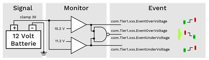 One monitor for battery monitoring with two events
Figure 2: One monitor for battery monitoring with two events
4. Examining the Operation-Cycle in DTC Management
What is the role of the operation cycle in the creation and recovery of DTCs? The operation cycle is a defined cycle in the vehicle that acts as a pulse for DTCs, ensuring their creation and recovery based on dynamic status defined in the UDS standard.
The operation cycle is a defined cycle in the vehicle that acts as a pulse for DTC creation and recovery. This section examines the role of the operation cycle in DTC management, focusing on its dynamic status defined in the UDS standard.
4.1. Defining the Operation-Cycle
How is the operation cycle defined in a vehicle, and what is its purpose in DTC management? The operation cycle is a defined sequence of events in a vehicle that triggers DTC creation and recovery, ensuring accurate fault detection and resolution.
The operation cycle is a defined sequence of events in the vehicle that triggers DTC creation and recovery. It ensures that DTCs are created and also recover again based on the vehicle’s operational status.
Key aspects of the operation cycle include:
-
Defined Sequence: A predefined sequence of events.
-
DTC Creation: Triggering the creation of DTCs based on fault detection.
-
DTC Recovery: Allowing DTCs to recover if the fault is no longer present.
The operation cycle acts as a pulse for DTC management, ensuring that DTCs accurately reflect the vehicle’s current state.
4.2. Dynamic Status of DTCs (ISO 14229-1:2013)
How does the dynamic status of DTCs, as defined in ISO 14229-1:2013, influence their lifecycle? The dynamic status of DTCs, as defined in ISO 14229-1:2013, determines their lifecycle stages, including pending, confirmed, and cleared, ensuring accurate fault tracking and management.
Each DTC has a dynamic status defined in ISO 14229-1:2013 (UDS standard). Bits 0 to 6 of the StatusOfDTC describe where the DTC is currently located in its lifecycle.
Key aspects of the dynamic status include:
-
Pending: The DTC is currently being evaluated.
-
Confirmed: The DTC has been confirmed as a fault.
-
Cleared: The DTC has been cleared, indicating that the fault is no longer present.
The dynamic status ensures that DTCs are accurately tracked and managed throughout their lifecycle.
4.3. Example of Dynamic DTC Behavior
Can you provide an example of how a DTC’s status changes dynamically within the operation cycle? An example illustrates how a DTC’s status changes dynamically within the operation cycle, from pending to confirmed and potentially cleared, based on fault detection and persistence.
Consider a DTC for low battery voltage. The operation cycle starts with “ignition on.” If the battery voltage is below a predefined threshold, the DTC enters a “pending” state. If the low voltage persists for a certain period, the DTC transitions to a “confirmed” state. If the battery voltage returns to normal and remains stable for a certain period, the DTC is “cleared.”
This example illustrates how the dynamic status of a DTC changes based on the vehicle’s operational status and the persistence of the fault.
4.4. Implications for Diagnostic Strategies
How does understanding the operation cycle and DTC dynamic status improve diagnostic strategies? Understanding the operation cycle and DTC dynamic status enables more effective diagnostic strategies, ensuring accurate fault identification, efficient troubleshooting, and optimized vehicle maintenance.
Understanding the operation cycle and the dynamic status of DTCs is crucial for developing effective diagnostic strategies. By knowing how DTCs are created, managed, and cleared, technicians can:
-
Accurately diagnose faults.
-
Efficiently troubleshoot issues.
-
Optimize vehicle maintenance.
This knowledge enables technicians to make informed decisions and resolve issues quickly and effectively.
4.5. Utilizing MERCEDES-DIAGNOSTIC-TOOL.EDU.VN for Operation Cycle Insights
How can MERCEDES-DIAGNOSTIC-TOOL.EDU.VN assist in understanding the operation cycle and DTC dynamic status? MERCEDES-DIAGNOSTIC-TOOL.EDU.VN offers detailed resources and expert guidance for understanding the operation cycle and DTC dynamic status, ensuring accurate diagnostics and optimized vehicle maintenance.
MERCEDES-DIAGNOSTIC-TOOL.EDU.VN provides comprehensive resources and expert guidance for understanding the operation cycle and the dynamic status of DTCs. This includes detailed explanations, practical examples, and tools for monitoring DTC status.
-
Operation Cycle Explanations: Detailed explanations of the operation cycle and its role in DTC management.
-
Dynamic Status Resources: Resources for understanding the dynamic status of DTCs.
-
Monitoring Tools: Tools for monitoring DTC status in real-time.
By leveraging these resources, technicians and engineers can enhance their understanding of the operation cycle and improve their ability to accurately diagnose and resolve issues.
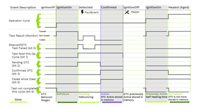 The dynamic behavior of DTC in the vehicle
Figure 3: The dynamic behavior of DTC in the vehicle
5. Exploring Error Memory: DTC Snapshot and Extended Data
What information is stored in error memory alongside DTCs, and why is it essential for complex error analysis? Error memory stores DTC snapshot data (freeze frames) and extended data, providing essential environmental conditions and historical context for complex error analysis.
An error code with status is sufficient for simple errors. For more complex errors, additional information is required for a more precise analysis. This section explores the error memory, focusing on DTC snapshot data (freeze frames) and extended data.
5.1. DTC Snapshot Data (Freeze Frames)
What is DTC snapshot data, and how does it aid in diagnosing vehicle issues? DTC snapshot data captures measured values at the time of a fault, providing crucial information for accurate diagnostics and troubleshooting.
The retrieval of measured values is already possible without DTCs via the ReadDataByIdentifier UDS service. For a meaningful analysis, the measured values must match the exact time of the triggering event. If a monitor reports “Failed,” the relevant DIDs (Data Identifiers) are temporarily stored with their measured values. This is known as snapshot data or freeze frames.
Key aspects of DTC snapshot data include:
-
Measured Values: Capturing relevant measured values at the time of the event.
-
Data Identifiers (DIDs): Using DIDs to identify the stored data.
-
Temporal Context: Providing a temporal context for the error, enabling more accurate analysis.
Snapshot data provides a valuable snapshot of the vehicle’s state at the time of the fault, enabling technicians to diagnose issues more effectively.
5.2. Details of Snapshot Data Structure
How is the data structure of snapshot data organized, and how does it relate to ODX? The data structure of snapshot data corresponds to a sequence of DIDs from the ReadDataByIdentifier service, with significant overlap with ODX for consistent data interpretation.
The data structure of a snapshot record corresponds to a sequence of individual DIDs from the ReadDataByIdentifier service. There is a large overlap with ODX. If the DIDs used for a DTC and their data structures are known, the ODX data for readDataByIdentifier and readDTC can be generated from the DEXT information and vice versa.
Key aspects of the snapshot data structure include:
-
DID Sequence: A sequence of individual DIDs from the ReadDataByIdentifier service.
-
ODX Overlap: Significant overlap with ODX, ensuring consistent data interpretation.
-
Data Generation: Ability to generate ODX data from DEXT information and vice versa.
The standardized data structure ensures that snapshot data can be easily interpreted by diagnostic tools, facilitating efficient troubleshooting.
5.3. Extended Data
What is DTC extended data, and what type of information does it contain? DTC extended data contains additional information about a DTC, such as cycle counters, aging counters, and time of last occurrences, providing a comprehensive view for fault analysis.
The Extended Data Block contains additional information about a DTC, such as cycle counters, aging counters, time of last occurrences, and dynamic data of algorithms that are not already contained in the FreezeFrame data.
Key aspects of extended data include:
-
Cycle Counters: Counting the number of cycles the DTC has been active.
-
Aging Counters: Tracking the age of the DTC.
-
Time of Last Occurrences: Recording the time of the last occurrence of the DTC.
-
Dynamic Data: Including dynamic data of algorithms not already contained in freeze frame data.
Extended data provides a more comprehensive view of the DTC, enabling technicians to analyze faults in greater detail.
5.4. Structure of Extended Data Block
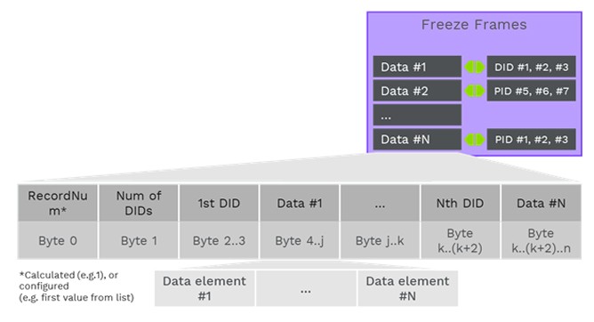
How is the structure of the extended data block organized, and how is the data interpreted? The extended data block is structured with a 1-byte record number specifying the data structure, enabling unambiguous interpretation of up to 255 stored ExtendedDataRecords.
Similar to the DIDs, a 1-byte record number specifies the data structure of the Extended Data block. Up to 255 stored ExtendedDataRecords can exist for a DTC. The interpretation of the data is unambiguously determined by its RecordNumber.
Key aspects of the extended data block structure include:
-
Record Number: A 1-byte record number specifying the data structure.
-
Multiple Records: Ability to store up to 255 ExtendedDataRecords for a DTC.
-
Data Interpretation: Unambiguous interpretation of data based on the RecordNumber.
The structured organization of the extended data block ensures that diagnostic tools can accurately interpret the data, facilitating efficient fault analysis.
5.5. Utilizing MERCEDES-DIAGNOSTIC-TOOL.EDU.VN for Error Memory Analysis
How can MERCEDES-DIAGNOSTIC-TOOL.EDU.VN assist in analyzing error memory data, including snapshot and extended data? MERCEDES-DIAGNOSTIC-TOOL.EDU.VN offers detailed resources and expert guidance for analyzing error memory data, ensuring accurate diagnostics and optimized vehicle maintenance.
MERCEDES-DIAGNOSTIC-TOOL.EDU.VN provides comprehensive resources and expert guidance for analyzing error memory data, including snapshot data and extended data. This includes detailed explanations of the data structures, practical examples of their application, and tools for interpreting the data.
-
Data Structure Explanations: Detailed explanations of the data structures of snapshot data and extended data.
-
Practical Examples: Real-world examples of how these data are used in vehicle diagnostics.
-
Interpretation Tools: Tools for interpreting snapshot data and extended data.
By leveraging these resources, technicians and engineers can enhance their ability to accurately analyze error memory data and resolve issues effectively.
6. Further DTC Relevant Information: Severity, Debouncing, and Function Inhibit
What additional DTC-related information is critical for comprehensive vehicle diagnostics and maintenance? Additional critical DTC-related information includes severity, debouncing, malfunction indicator, and function inhibit, essential for comprehensive vehicle diagnostics and maintenance.
The description of snapshot data and extended data are very similar for ODX and DEXT. However, there is a large amount of additional information in DEXT, such as severity, debouncing, malfunction indicator, and function inhibit, which is not contained in ODX but is mandatory for a DTC in an ECU. This section explores these additional aspects.
6.1. Severity
How does the severity level of a DTC impact diagnostic and repair decisions? The severity level of a DTC guides diagnostic and repair decisions by indicating the urgency and potential impact of the fault on vehicle operation and safety.
The severity level of a DTC indicates the potential impact of the fault on vehicle operation and safety. It helps technicians prioritize diagnostic and repair efforts. For example, a DTC with a high severity level may indicate a critical issue that requires immediate attention, while a DTC with a low severity level may indicate a minor issue that can be addressed later.
6.2. Debouncing
How does debouncing influence the accuracy and reliability of DTC reporting? Debouncing enhances the accuracy and reliability of DTC reporting by preventing transient issues from triggering false alarms, ensuring only persistent faults are flagged.
Debouncing is a strategy used to prevent transient issues from triggering false DTCs. It ensures that only persistent faults are flagged, improving the accuracy and reliability of DTC reporting. Different debouncing strategies, such as time-based, counter-based, and internal debouncing, can be used depending on the specific requirements of the system.
6.3. Malfunction Indicator
What is the role of the malfunction indicator in alerting drivers to potential vehicle issues? The malfunction indicator alerts drivers to potential vehicle issues by illuminating a warning light, prompting them to seek diagnostic and repair services.
The malfunction indicator (MI), also known as the check engine light, is a warning light that illuminates when a DTC is triggered. It alerts drivers to potential issues with their vehicle and prompts them to seek diagnostic and repair services. The MI is an essential part of the vehicle’s diagnostic system, providing a visual indication of potential problems.
6.4. Function Inhibit
How does function inhibit contribute to vehicle safety and performance in response to DTCs? Function inhibit ensures vehicle safety and performance by deactivating specific functions when a DTC is detected, preventing further damage or hazardous operation.
Function inhibit is a mechanism used to deactivate certain vehicle functions when a DTC is detected. This is done to prevent further damage to the vehicle or to ensure safe operation. For example, if a DTC is triggered in the ABS system, the function inhibit may deactivate the ABS to prevent erratic braking behavior.
6.5. Utilizing MERCEDES-DIAGNOSTIC-TOOL.EDU.VN for Comprehensive DTC Understanding
How can MERCEDES-DIAGNOSTIC-TOOL.EDU.VN help in understanding and utilizing additional DTC-related information like severity, debouncing, malfunction indicator, and function inhibit? MERCEDES-DIAGNOSTIC-TOOL.EDU.VN offers detailed resources and expert guidance for understanding additional DTC-related information, ensuring accurate diagnostics and optimized vehicle maintenance.
MERCEDES-DIAGNOSTIC-TOOL.EDU.VN provides comprehensive resources and expert guidance for understanding additional DTC-related information, such as severity, debouncing, malfunction indicator, and function inhibit. This includes detailed explanations of these concepts, practical examples of their application, and tools for configuring and managing them.
-
Severity Explanations: Detailed explanations of DTC severity levels and their implications.
-
Debouncing Strategies: Resources for understanding and implementing effective debouncing strategies.
-
Malfunction Indicator Information: Information on the role and function of the malfunction indicator.
-
Function Inhibit Details: Details on how function inhibit is used to ensure vehicle safety and performance.
By leveraging these resources, technicians and engineers can enhance their understanding of DTC-related information and improve their ability to accurately diagnose and resolve issues.
7. The Diagnostic Communication Manager (DCM) in DTC Handling
How does the Diagnostic Communication Manager facilitate the transmission of DTC data to the tester? The Diagnostic Communication Manager encodes and transmits DTC data to the tester via the vehicle bus, enabling accurate diagnostics and troubleshooting.
The last step on the way to the tester is the DCM, which is responsible for encoding and transmitting the data to the tester. This section explores the role of the DCM in DTC handling.
7.1. Encoding and Transmission of DTC Data
How does the DCM encode and transmit DTC data to ensure accurate communication with diagnostic tools? The DCM encodes DTC data as a two or three-byte value according to the set DTC format and transmits it via the vehicle bus for accurate communication with diagnostic tools.
With the ReadDTC (0x19) UDS service, a DTC is encoded as a two or three-byte value according to the set DTC format and transmitted via the vehicle bus. The DCM ensures that the data is properly formatted and transmitted, enabling accurate communication with diagnostic tools.
7.2. UDS Service 0x19 (ReadDTC)
What is the function of UDS service 0x19 (ReadDTC) in retrieving DTC information? UDS service 0x19 (ReadDTC) retrieves DTC information, including freeze frame and extended data, for diagnostic analysis and troubleshooting.
The UDS service 0x19 (ReadDTC) is used to retrieve DTC information from the ECU. Depending on the selected sub-function, the freeze frame or the corresponding extended data information must be decoded in the tester in addition to the DTC. This service is essential for accessing the information needed to diagnose and resolve vehicle issues.
7.3. Ensuring Identical Coding and Decoding
Why is it essential for the coding of UDS data in the ECU to be identical to the decoding in the diagnostic tester? Identical coding and decoding of UDS data between the ECU and diagnostic tester ensure accurate data interpretation and reliable diagnostics.
The coding of the UDS data in the ECU, based on DEXT, must be identical to the decoding based on ODX. This ensures that the diagnostic tester accurately interprets the data transmitted by the ECU, enabling reliable diagnostics and troubleshooting.
7.4. Challenges for the Diagnostic Tester
What challenges does the diagnostic tester face in accurately interpreting DTC data? The diagnostic tester faces challenges in identifying the specific vehicle, selecting the appropriate VehicleInformationTable, and determining the exact software version of the ECUs for accurate DTC data interpretation.
There are additional challenges for the diagnostic tester. First, it must identify the specific vehicle and select the appropriate VehicleInformationTable (VIT) from ODX. Then, the exact software version of the ECUs installed in the vehicle, or in the case of Adaptive AUTOSAR, the Software Cluster (SWC), is determined by means of variant identification. For this reason, the ODX data of each ECU contains the necessary interpretation for the various software variants.
7.5. Utilizing MERCEDES-DIAGNOSTIC-TOOL.EDU.VN for DCM Insights
How can MERCEDES-DIAGNOSTIC-TOOL.EDU.VN assist in understanding the role of the Diagnostic Communication Manager? MERCEDES-DIAGNOSTIC-TOOL.EDU.VN offers detailed resources and expert guidance for understanding the role of the Diagnostic Communication Manager, ensuring accurate diagnostics and optimized vehicle maintenance.
MERCEDES-DIAGNOSTIC-TOOL.EDU.VN provides comprehensive resources and expert guidance for understanding the role of the Diagnostic Communication Manager, including detailed explanations of the encoding and transmission process, the UDS service 0x19, and the challenges faced by the diagnostic tester.
-
DCM Explanations: Detailed explanations of the role and function of the Diagnostic Communication Manager.
-
UDS Service 0x19 Information: Information on the UDS service 0x19 and its use in retrieving DTC information.
-
Tester Challenges: Insights into the challenges faced by the diagnostic tester in accurately interpreting DTC data.
By leveraging these resources, technicians and engineers can enhance their understanding of the DCM and improve their ability to accurately diagnose and resolve issues.
8. The DTC in the Diagnose Tester (ODX)
How are DTCs and associated data handled within the diagnostic tester using the ODX format? DTCs and associated data are decoded and interpreted within the diagnostic tester using the ODX format, ensuring accurate diagnostics and troubleshooting.
Depending on the selected 0x19-ReadDTC sub-function, the freeze frame or the corresponding ExtendedData information must be decoded in the tester in addition to the DTC. Of