Connecting the CAN low wire to OBD2 is crucial for accessing vehicle data and diagnosing issues, and at MERCEDES-DIAGNOSTIC-TOOL.EDU.VN, we offer clear guidance to simplify this process. Proper connection enables effective communication with your Mercedes-Benz’s systems, empowering you with essential insights for maintenance and performance optimization. Dive in to explore Mercedes diagnostic tools, hidden feature activation, and comprehensive repair guides.
1. Understanding the Basics of CAN Bus and OBD2
What exactly is the Controller Area Network (CAN) bus, and how does it relate to the On-Board Diagnostics II (OBD2) port in your Mercedes-Benz? Let’s break it down simply.
The CAN bus is a communication system that allows various electronic control units (ECUs) within your vehicle to talk to each other. These ECUs control everything from the engine and transmission to the brakes and airbags. Instead of having separate wires for each connection, the CAN bus uses a two-wire system—CAN High and CAN Low—to transmit data efficiently. According to Robert Bosch GmbH, the CAN protocol was developed to reduce wiring complexity and improve reliability in automotive systems.
The OBD2 port, typically located under the dashboard, is your gateway to accessing this CAN bus data. It’s a standardized interface that allows diagnostic tools to communicate with the vehicle’s ECUs, retrieve diagnostic trouble codes (DTCs), monitor real-time data, and perform various tests. The Society of Automotive Engineers (SAE) defines the standards for OBD2, ensuring compatibility across different vehicle makes and models.
2. Identifying the CAN Low Wire in Your Mercedes-Benz
Where can you find the CAN Low wire in your Mercedes-Benz, and how do you identify it correctly?
In most Mercedes-Benz vehicles, the CAN bus wires are part of the OBD2 port wiring harness. The CAN Low wire is typically green, though this can vary depending on the model year and specific wiring configuration. Always consult your vehicle’s wiring diagram to confirm the correct wire.
The OBD2 port has a standardized pinout, with specific pins designated for CAN High and CAN Low. According to the OBD2 standard, pin 14 is CAN High, and pin 6 is CAN Low. However, it’s essential to double-check this information against your vehicle’s service manual or wiring diagram to avoid any misconnections.
3. Tools and Equipment Needed for Connecting CAN Low to OBD2
What tools and equipment do you need to connect the CAN Low wire to your Mercedes-Benz’s OBD2 port safely and effectively?
- OBD2 Connector or Adapter: A standard OBD2 connector or adapter cable is necessary to interface with the vehicle’s OBD2 port. Ensure it is compatible with your Mercedes-Benz model.
- Wiring Diagram: A detailed wiring diagram for your specific Mercedes-Benz model is crucial for identifying the correct CAN Low wire and OBD2 pinout.
- Multimeter: A multimeter is used to test the continuity and voltage of the CAN bus wires, ensuring proper connection and signal integrity.
- Wire Strippers/Crimpers: These tools are needed to strip the insulation from the wires and crimp the connectors securely.
- Connectors/Terminals: Appropriate connectors or terminals are required to establish a reliable connection between the CAN Low wire and the OBD2 port.
- Soldering Iron and Solder (Optional): For a more permanent and secure connection, a soldering iron and solder can be used.
- Heat Shrink Tubing (Optional): Heat shrink tubing can provide insulation and protection for the soldered connections.
- Safety Glasses and Gloves: Always wear safety glasses and gloves to protect yourself from potential hazards during the wiring process.
4. Step-by-Step Guide to Connecting CAN Low Wire to OBD2
How do you connect the CAN Low wire to the OBD2 port in your Mercedes-Benz? Follow these steps for a successful connection:
- Locate the OBD2 Port: Find the OBD2 port, usually located under the dashboard on the driver’s side.
- Identify CAN Low Wire: Using your vehicle’s wiring diagram, identify the CAN Low wire. It is often green but confirm with the diagram.
- Prepare the Wires: Strip a small section of insulation from the CAN Low wire and the corresponding wire from your OBD2 connector or adapter.
- Connect the Wires:
- Using Connectors: Attach the appropriate connectors or terminals to the stripped ends of the wires. Securely connect the CAN Low wire to the correct pin on the OBD2 connector (pin 6).
- Soldering (Optional): If soldering, carefully solder the CAN Low wire to the corresponding pin on the OBD2 connector. Allow the solder to cool, then cover the connection with heat shrink tubing for insulation.
- Test the Connection: Use a multimeter to test the continuity between the CAN Low wire and the OBD2 port. Also, check the voltage to ensure it falls within the specified range (typically around 2.5V).
- Secure the Connection: Ensure all connections are secure and properly insulated to prevent short circuits or signal interference.
- Verify Functionality: Connect a diagnostic tool to the OBD2 port and verify that it can communicate with the vehicle’s ECUs. Check for any error codes or communication issues.
5. Common Issues and Troubleshooting Tips
What are some common issues you might encounter when connecting the CAN Low wire, and how can you troubleshoot them?
- No Communication:
- Issue: Diagnostic tool cannot communicate with the vehicle’s ECUs.
- Troubleshooting:
- Check Wiring: Verify that the CAN Low wire is connected to the correct pin on the OBD2 port and that the connection is secure.
- Check Voltage: Use a multimeter to check the voltage on the CAN bus wires. CAN High should be around 3.5V, and CAN Low should be around 1.5V when the system is active.
- Check Ground: Ensure that the ground connection is properly established.
- Check Diagnostic Tool: Make sure your diagnostic tool is compatible with your Mercedes-Benz model and supports the CAN bus protocol.
- Intermittent Connection:
- Issue: The connection is unstable, causing intermittent communication errors.
- Troubleshooting:
- Check Connectors: Ensure that the connectors are properly crimped and securely attached.
- Check Wiring Harness: Inspect the wiring harness for any signs of damage or corrosion.
- Secure Wires: Use zip ties or electrical tape to secure the wires and prevent them from moving around.
- Error Codes:
- Issue: Diagnostic tool reports error codes related to CAN bus communication.
- Troubleshooting:
- Record Codes: Note the specific error codes and research their meaning in your vehicle’s service manual or online resources.
- Clear Codes: Attempt to clear the error codes using the diagnostic tool.
- Test Components: If the codes persist, test the individual components connected to the CAN bus, such as sensors and ECUs.
6. Understanding CAN Bus Diagnostics with Mercedes Diagnostic Tools
How do Mercedes diagnostic tools utilize the CAN bus for comprehensive vehicle diagnostics?
Mercedes diagnostic tools, such as the XENTRY system, use the CAN bus to communicate with the vehicle’s various ECUs, retrieve diagnostic trouble codes (DTCs), monitor real-time data, and perform advanced tests. According to Mercedes-Benz, these tools are designed to provide technicians with detailed insights into the vehicle’s operation and identify potential issues.
The CAN bus allows the diagnostic tool to access a wide range of data, including engine parameters, transmission data, ABS information, airbag status, and more. By analyzing this data, technicians can diagnose problems accurately and efficiently.
For example, if the engine control unit (ECU) detects a fault in the fuel injection system, it will store a DTC in its memory. The diagnostic tool can retrieve this code via the CAN bus and provide the technician with information about the nature and location of the fault.
7. Unlocking Hidden Features via CAN Bus
Can you unlock hidden features in your Mercedes-Benz by accessing the CAN bus, and how is this done?
Yes, it is possible to unlock hidden features in your Mercedes-Benz by accessing the CAN bus and modifying the vehicle’s software. Many modern vehicles have features that are disabled by default but can be activated through coding or programming.
This process typically involves using a specialized diagnostic tool or software to communicate with the vehicle’s ECUs and modify the relevant parameters. For example, you might be able to enable features like:
- Comfort Closing: Automatically close all windows and the sunroof when locking the vehicle.
- Cornering Lights: Activate the fog lights to illuminate the direction of the turn at low speeds.
- Enhanced Display Options: Display additional information on the instrument cluster or infotainment screen.
However, it’s important to note that modifying the vehicle’s software can be risky and may void your warranty. Always proceed with caution and consult with a qualified technician before attempting to unlock hidden features.
8. Safety Precautions When Working with CAN Bus
What safety precautions should you take when working with the CAN bus in your Mercedes-Benz?
- Disconnect the Battery: Before working on any electrical components, disconnect the negative terminal of the battery to prevent electrical shocks and short circuits.
- Use Proper Tools: Use high-quality, insulated tools to avoid damaging the wiring or causing electrical hazards.
- Follow Wiring Diagrams: Always refer to the vehicle’s wiring diagram to ensure correct connections and avoid miswiring.
- Avoid Short Circuits: Be careful not to create short circuits by accidentally touching wires together or grounding them improperly.
- Protect Against Static Electricity: Static electricity can damage sensitive electronic components. Ground yourself before touching any wires or connectors.
- Test Before Finalizing: Before reassembling the vehicle, test all connections and ensure that everything is working properly.
- Consult Professionals: If you are not comfortable working with the CAN bus or vehicle electronics, consult with a qualified technician.
9. Alternative Methods for Accessing Vehicle Data
Are there alternative methods for accessing vehicle data if you don’t want to directly connect to the CAN Low wire?
Yes, there are several alternative methods for accessing vehicle data without directly connecting to the CAN Low wire:
- OBD2 Scanners: Standard OBD2 scanners can read diagnostic trouble codes (DTCs) and monitor real-time data without requiring direct access to the CAN bus wires.
- Wireless OBD2 Adapters: Wireless OBD2 adapters, such as Bluetooth or Wi-Fi dongles, can transmit vehicle data to your smartphone or tablet, allowing you to monitor performance and diagnose issues remotely.
- Contactless CAN Bus Readers: Contactless CAN bus readers use induction to read data from the CAN High and CAN Low wires without physically connecting to them. These devices are non-invasive and can be useful in situations where you don’t want to disturb the vehicle’s wiring.
- Data Loggers: Data loggers can record CAN bus data over time, allowing you to analyze vehicle performance and diagnose intermittent issues. Some data loggers can also transmit data wirelessly to a computer or cloud-based platform.
10. How MERCEDES-DIAGNOSTIC-TOOL.EDU.VN Can Help
How can MERCEDES-DIAGNOSTIC-TOOL.EDU.VN assist you with your Mercedes-Benz diagnostic and repair needs?
At MERCEDES-DIAGNOSTIC-TOOL.EDU.VN, we are dedicated to providing Mercedes-Benz owners and technicians with the resources and support they need to diagnose, repair, and maintain their vehicles effectively. Our website offers a wealth of information, including:
- Detailed Diagnostic Guides: Step-by-step guides for diagnosing common issues in Mercedes-Benz vehicles, including information on how to use diagnostic tools and interpret error codes.
- Wiring Diagrams: Comprehensive wiring diagrams for various Mercedes-Benz models, helping you identify the correct wires and connections for your specific vehicle.
- Repair Tutorials: Video tutorials and written instructions for performing common repairs, from replacing sensors to troubleshooting electrical problems.
- Hidden Feature Activation: Information on how to unlock hidden features in your Mercedes-Benz, along with guidance on the necessary tools and software.
- Community Forum: A community forum where you can connect with other Mercedes-Benz owners and technicians, ask questions, and share your experiences.
- Expert Support: Access to our team of experienced Mercedes-Benz technicians, who can provide personalized support and guidance for your specific needs.
Whether you’re a seasoned mechanic or a DIY enthusiast, MERCEDES-DIAGNOSTIC-TOOL.EDU.VN is your go-to resource for all things Mercedes-Benz diagnostics and repair.
11. CAN Bus Variants and Their Applications
What are the different variants of CAN bus, and where are they typically used?
- Low-Speed CAN: Also known as fault-tolerant CAN, this variant is used for non-critical applications where fault tolerance is essential. However, it is increasingly being replaced by LIN bus.
- High-Speed CAN: Also known as Classical CAN, this is the most common variant used in automotive and machinery applications. It is the primary focus of this article.
- CAN FD (Flexible Data-Rate): This variant offers longer payloads and faster speeds compared to Classical CAN, but its adoption remains limited.
- CAN XL: This variant offers even longer payloads and faster speeds, bridging the gap between CAN and Automotive Ethernet. It is designed for advanced automotive and industrial applications.
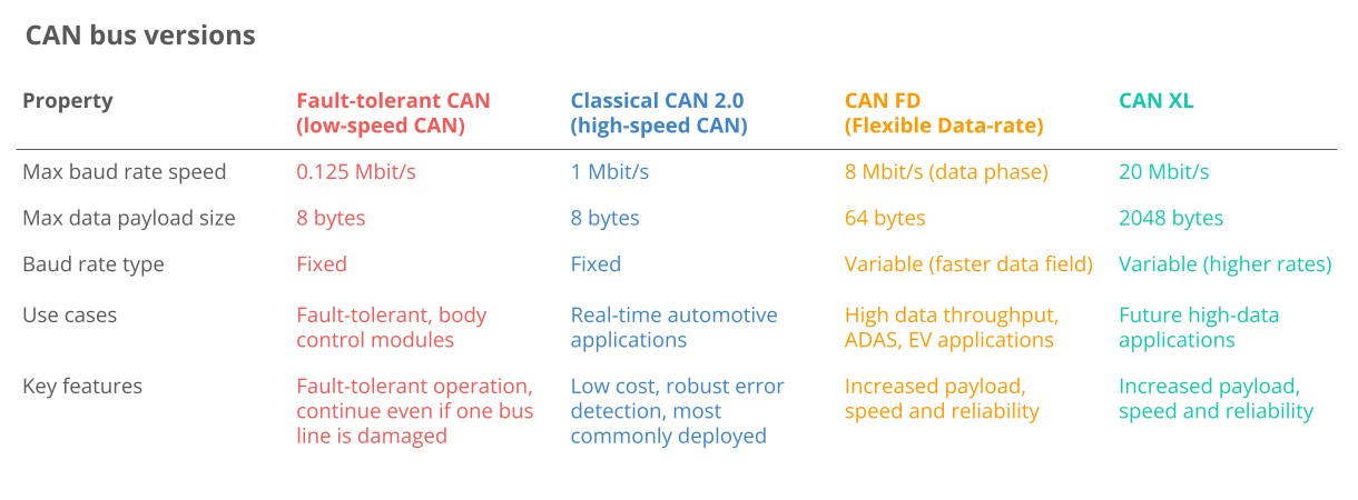 Classical CAN FD XL Variants canbus
12. Relationship Between CAN Bus and Other Automotive Networks
How does CAN bus relate to other automotive networks like LIN bus, FlexRay, and Automotive Ethernet?
- LIN Bus: LIN bus is a lower-cost supplement to CAN bus networks, used for non-critical vehicle functions such as air conditioning and door functionality. It consists of a LIN master and up to 16 slave nodes.
- FlexRay: FlexRay offers higher speeds and fault tolerance compared to CAN bus but is more costly. It is standardized as per ISO 17458-1 and ISO 17458-5.
- Automotive Ethernet: This is increasingly used in the automotive sector to support high bandwidth requirements for ADAS, infotainment systems, and cameras. While it offers higher data transfer rates, it lacks some of the safety and performance features of CAN.
13. Benefits of CAN Bus in Modern Vehicles
What are the key benefits of using CAN bus in modern vehicles?
- Simple and Low Cost: CAN bus reduces wiring complexity and costs by allowing ECUs to communicate via a single system instead of direct analog signal lines.
- Easy Access: The CAN bus provides a single point of entry for communicating with all network ECUs, enabling centralized diagnostics, data logging, and configuration.
- Extremely Robust: The system is robust against electrical disturbances and electromagnetic interference, making it ideal for safety-critical applications.
- Efficient: CAN frames are prioritized by ID, ensuring that top-priority data gets immediate bus access without interrupting other frames.
14. Brief History of CAN Bus Development
What is the history of CAN bus, from its inception to its current status?
- Pre-CAN: Car ECUs relied on complex point-to-point wiring.
- 1986: Bosch developed the CAN protocol as a solution.
- 1991: Bosch published CAN 2.0 (CAN 2.0A: 11-bit, 2.0B: 29-bit).
- 1993: CAN is adopted as an international standard (ISO 11898).
- 2003: ISO 11898 becomes a standard series.
- 2012: Bosch released CAN FD 1.0 (flexible data rate).
- 2015: The CAN FD protocol is standardized (ISO 11898-1).
- 2016: The physical CAN layer for data rates up to 5 Mbit/s is standardized in ISO 11898-2.
- 2018: CiA starts development of CAN XL.
- 2024: CAN XL is standardized (ISO 11898-1:2024, 11898-2:2024).
15. Future Trends in CAN Bus Technology
What are the future trends and developments expected in CAN bus technology?
- Need for Speed: Demand for higher data rates may drive the transition towards CAN FD, CAN XL, or Automotive Ethernet.
- Connected Vehicles: The rise of cloud computing and vehicle telematics may enable predictive maintenance and remote troubleshooting, but also introduce cybersecurity risks.
- Open vs. Closed: A push towards “Open Source” and “Right to Repair” may conflict with OEM demands for keeping data proprietary for subscription-based microservices.
16. CAN Bus Physical and Data Link Layers
What are the physical and data link layers of the CAN bus protocol?
- Physical Layer (ISO 11898-2): Defines cable types, electrical signal levels, node requirements, and cable impedance.
- Data Link Layer (ISO 11898-1): Defines CAN frame formats, error handling, and data transmission, ensuring data integrity.
17. Key Components of a CAN Frame
What are the key components of a CAN frame, and what do they represent?
- SOF (Start of Frame): Indicates the beginning of a CAN frame.
- ID (Identifier): Specifies the frame’s priority; lower values have higher priority.
- RTR (Remote Transmission Request): Indicates whether a node sends data or requests data from another node.
- Control: Contains the Identifier Extension Bit (IDE) and the Data Length Code (DLC).
- Data: Contains the data bytes, including CAN signals.
- CRC (Cyclic Redundancy Check): Ensures data integrity.
- ACK (Acknowledge): Indicates if the node has acknowledged and received the data correctly.
- EOF (End of Frame): Marks the end of the CAN frame.
18. Different Types of CAN Frames
What are the different types of CAN frames, and what are their purposes?
- Data Frame: Carries data from a sender CAN node to one or more receiver nodes.
- Error Frame: Indicates the detection of a communication error.
- Remote Frame: Requests specific data from a CAN node.
- Overload Frame: Provides additional delay between CAN frames if needed.
19. Understanding Higher-Layer CAN Protocols
What are higher-layer CAN protocols, and why are they necessary?
Higher-layer protocols provide additional details on how data is communicated between CAN nodes, including handling messages larger than 8 bytes and decoding raw data. Examples include OBD2, UDS, CCP/XCP, CANopen, SAE J1939, NMEA 2000, and ISOBUS.
20. Common Higher-Layer Protocols and Their Applications
What are some common higher-layer CAN protocols and their applications?
- OBD2: Used in cars and trucks for diagnostics, maintenance, and emissions tests.
- UDS (Unified Diagnostic Services): Used in automotive ECUs for diagnostics, firmware updates, and routine testing.
- CCP/XCP: Used for ECU calibration, measurement, and flashing.
- CANopen: Used in embedded control applications, including industrial automation.
- SAE J1939: Used in heavy-duty vehicles.
- NMEA 2000: Used in the maritime industry for connecting engines, instruments, and sensors on boats.
- ISOBUS: Used in agriculture and forestry machinery.
21. Steps for Logging CAN Bus Data
What are the critical steps for logging raw CAN bus data?
- Select the Right Hardware: Choose a CAN bus data logger that suits your needs.
- Identify What Adapter Cable to Use: Determine the appropriate adapter for your application (e.g., OBD2, J1939, M12).
- Configure and Connect Your Device: Match the baud rate and configure any necessary request messages.
- Review Your Raw CAN Data: Analyze the resulting log file, which contains timestamped CAN frames with IDs and data payloads.
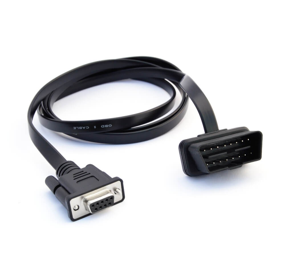 On Board Diagnostic OBD2 Connector Adapter
22. Understanding CAN Signal Extraction for Decoding Raw Data
How do you decode raw CAN data into physical values?
- Understand CAN Signal Extraction: Each CAN frame contains CAN signals in the data payload. Extracting these signals requires information about byte order, bit start, bit length, offset, and scale.
- Get the Relevant DBC File: A DBC (CAN database) file contains the information needed to decode raw CAN data.
- Use a Software/API Tool: Use a software or API tool that supports your log file format and DBC files for decoding.
23. Popular Use Cases for Logging CAN Data
What are some popular use cases for logging CAN bus data?
- Logging/Streaming Data from Cars: Used for reducing fuel costs, improving driving, testing prototype parts, and insurance.
- Heavy-Duty Fleet Telematics: Used in fleet management to reduce costs and improve safety.
- Predictive Maintenance: Used to monitor vehicles and machinery via IoT CAN loggers to predict and avoid breakdowns.
- Vehicle/Machine Blackbox: Used as a “blackbox” for vehicles or equipment to provide data for disputes or diagnostics.
24. FAQ Section: Addressing Common Questions About Connecting CAN Low Wire to OBD2
Q1: What is the CAN bus, and why is it important in Mercedes-Benz vehicles?
A1: The CAN bus is a communication network that allows various electronic components in your Mercedes-Benz to communicate with each other efficiently. It’s crucial for diagnostics, data logging, and unlocking hidden features, enhancing vehicle performance and maintenance.
Q2: How do I identify the CAN Low wire in my Mercedes-Benz?
A2: The CAN Low wire is typically green, but it’s essential to consult your vehicle’s wiring diagram to confirm. It is located at pin 6 of the OBD2 port.
Q3: What tools are needed to connect the CAN Low wire to the OBD2 port?
A3: You’ll need an OBD2 connector or adapter, wiring diagram, multimeter, wire strippers/crimpers, connectors/terminals, and optionally a soldering iron and heat shrink tubing.
Q4: What are the main benefits of connecting CAN Low to OBD2?
A4: Connecting CAN Low to OBD2 enables access to diagnostic information, allows for data logging, and facilitates the unlocking of hidden features, ultimately improving vehicle management and customization.
Q5: What should I do if my diagnostic tool cannot communicate after connecting the CAN Low wire?
A5: First, verify that the CAN Low wire is correctly connected to pin 6 on the OBD2 port and that the connection is secure. Check the voltage using a multimeter and ensure your diagnostic tool is compatible with your Mercedes-Benz model.
Q6: What are some common error codes related to CAN bus communication, and how can I resolve them?
A6: Common error codes indicate issues such as wiring problems, voltage discrepancies, or faulty connections. Research these codes using your vehicle’s service manual or online resources, and then inspect and correct any connection or wiring issues.
Q7: Can I unlock hidden features in my Mercedes-Benz by accessing the CAN bus?
A7: Yes, by using specialized diagnostic tools and software, you can modify parameters to enable features like comfort closing, cornering lights, and enhanced display options. Proceed cautiously and consult a professional before making any changes.
Q8: What safety precautions should I take when working with the CAN bus?
A8: Disconnect the battery, use insulated tools, follow wiring diagrams, avoid short circuits, protect against static electricity, and consult professionals if needed to ensure safety and prevent damage.
Q9: Are there alternative ways to access vehicle data without directly connecting to the CAN Low wire?
A9: Yes, alternatives include using OBD2 scanners, wireless OBD2 adapters, contactless CAN bus readers, and data loggers. These tools allow you to monitor and log data without direct wiring modifications.
Q10: How can MERCEDES-DIAGNOSTIC-TOOL.EDU.VN help with my Mercedes-Benz diagnostic needs?
A10: We offer detailed diagnostic guides, wiring diagrams, repair tutorials, information on unlocking hidden features, a community forum, and expert support to assist you in effectively diagnosing, repairing, and maintaining your Mercedes-Benz.
Conclusion
Connecting the CAN low wire to the OBD2 port of your Mercedes-Benz is a gateway to unlocking a wealth of diagnostic information, customization options, and performance enhancements. By following the steps outlined in this guide, you can confidently tackle this task and take control of your vehicle’s maintenance and optimization. Remember, MERCEDES-DIAGNOSTIC-TOOL.EDU.VN is here to support you with the resources and expertise you need to succeed.
Ready to take the next step? Contact us at MERCEDES-DIAGNOSTIC-TOOL.EDU.VN for personalized guidance and support on your Mercedes-Benz diagnostic and repair needs. Our experts are here to help you choose the right diagnostic tools, unlock hidden features, and ensure your vehicle performs at its best.
Contact Information:
- Address: 789 Oak Avenue, Miami, FL 33101, United States
- WhatsApp: +1 (641) 206-8880
- Website: MERCEDES-DIAGNOSTIC-TOOL.EDU.VN
Don’t hesitate to reach out today and discover how we can help you get the most out of your Mercedes-Benz.