Are you looking for information on how to wire an OBD1 distributor to an OBD2 harness? This guide from MERCEDES-DIAGNOSTIC-TOOL.EDU.VN will walk you through the process, providing you with the knowledge to confidently tackle this modification and ensure optimal performance for your vehicle. We’ll explore the necessary steps and considerations for adapting an older distributor to a newer vehicle, making the transition as smooth as possible. This includes distributor wiring, OBD1 to OBD2 conversion, and engine management systems.
Contents
- 1. Understanding the Basics of OBD1 and OBD2 Systems
- 1.1 Key Differences Between OBD1 and OBD2
- 1.2 How OBD2 Improves Diagnostic Capabilities
- 1.3 The Evolution of Engine Management Systems
- 2. Identifying the Necessary Components for the Conversion
- 2.1 Essential Components for OBD1 to OBD2 Distributor Conversion
- 2.2 Selecting the Right Adapter Harness
- 2.3 Importance of Quality Wiring Connectors
- 3. Step-by-Step Guide on Wiring OBD1 Distributor to OBD2 Harness
- 3.1 Preparing the OBD1 and OBD2 Harnesses
- 3.2 Making the Correct Wire Connections
- 3.3 Testing and Verifying the Connections
- 4. Detailed Wiring Diagrams and Pinout Configurations
- 4.1 OBD1 Distributor Pinout Diagram
- 4.2 OBD2 Harness Pinout Diagram
- 4.3 Example Wiring Diagram for OBD1 Distributor to OBD2 Harness Conversion
- 5. Troubleshooting Common Issues During the Wiring Process
- 5.1 Common Wiring Problems and Solutions
- 5.2 Addressing Sensor Failures
- 5.3 ECU Compatibility Issues
- 6. Advanced Techniques for Optimizing Engine Performance
- 6.1 ECU Tuning for Enhanced Performance
- 6.2 Ignition Timing Adjustments
- 6.3 Fuel System Modifications
- 7. Safety Precautions to Take During the Wiring Process
- 7.1 Disconnecting the Battery
- 7.2 Using Proper Safety Gear
- 7.3 Following Safety Procedures
- 8. Case Studies of Successful OBD1 to OBD2 Distributor Conversions
- 8.1 Case Study 1: 1996 Honda Prelude with JDM H22A Engine
- 8.2 Case Study 2: 1998 Acura Integra with B18C1 Engine
- 8.3 Case Study 3: 1994 Honda Civic with D16Z6 Engine
- 9. Benefits of Upgrading to an OBD2 System
- 9.1 Enhanced Diagnostic Capabilities
- 9.2 Improved Emissions Monitoring
- 9.3 Standardized Data Reporting
- 10. Frequently Asked Questions (FAQ)
- 10.1 Is it possible to wire an OBD1 distributor to an OBD2 harness?
- 10.2 What tools are needed for this conversion?
- 10.3 How do I identify the correct wires on the OBD1 distributor and OBD2 harness?
- 10.4 Can I use a pre-made adapter harness for this conversion?
- 10.5 What are the common issues that can occur during this conversion?
- 10.6 How do I test the connections after wiring the OBD1 distributor to the OBD2 harness?
- 10.7 Do I need to tune the ECU after this conversion?
- 10.8 What safety precautions should I take during the wiring process?
- 10.9 Where can I find reliable wiring diagrams and pinout configurations?
- 10.10 What are the benefits of upgrading to an OBD2 system?
Table of Contents
- Understanding the Basics of OBD1 and OBD2 Systems
- Identifying the Necessary Components for the Conversion
- Step-by-Step Guide on Wiring OBD1 Distributor to OBD2 Harness
- Detailed Wiring Diagrams and Pinout Configurations
- Troubleshooting Common Issues During the Wiring Process
- Advanced Techniques for Optimizing Engine Performance
- Safety Precautions to Take During the Wiring Process
- Case Studies of Successful OBD1 to OBD2 Distributor Conversions
- Benefits of Upgrading to an OBD2 System
- Frequently Asked Questions (FAQ)
1. Understanding the Basics of OBD1 and OBD2 Systems
What are the fundamental differences between OBD1 and OBD2 systems? Understanding the differences between OBD1 (On-Board Diagnostics 1) and OBD2 (On-Board Diagnostics 2) systems is crucial before attempting any wiring modifications. OBD1, used in vehicles manufactured before 1996, offers limited diagnostic capabilities, with each manufacturer implementing their own standards and connectors. OBD2, standardized in 1996, provides enhanced diagnostic features, a universal connector, and comprehensive data reporting.
1.1 Key Differences Between OBD1 and OBD2
| Feature | OBD1 | OBD2 |
|---|---|---|
| Standardization | No universal standard | Standardized diagnostic parameters and connector |
| Diagnostic Capability | Limited, manufacturer-specific codes | Enhanced, comprehensive, and standardized diagnostic codes |
| Connector Type | Various, manufacturer-dependent | Universal 16-pin connector |
| Data Reporting | Limited data parameters | Extensive real-time data parameters |
| Compliance | No mandated emissions compliance | Mandated emissions compliance |
1.2 How OBD2 Improves Diagnostic Capabilities
OBD2 systems offer significant improvements in diagnostic capabilities compared to OBD1. According to a study by the Environmental Protection Agency (EPA), OBD2 enhances the accuracy and reliability of emissions monitoring, leading to better identification and resolution of vehicle issues. The standardized diagnostic trouble codes (DTCs) and real-time data parameters allow technicians to quickly pinpoint problems, reducing diagnostic time and repair costs.
1.3 The Evolution of Engine Management Systems
The evolution of engine management systems from OBD1 to OBD2 represents a major advancement in automotive technology. OBD1 systems primarily focused on basic engine control, while OBD2 systems integrate more sophisticated features like fuel trim adjustments, misfire detection, and comprehensive emissions monitoring. As noted in a SAE International study, these enhancements improve fuel efficiency, reduce emissions, and enhance overall vehicle performance.
2. Identifying the Necessary Components for the Conversion
What components are essential for wiring an OBD1 distributor to an OBD2 harness? To successfully wire an OBD1 distributor to an OBD2 harness, you will need several key components. These include the OBD1 distributor, OBD2 harness, adapter harness, wiring connectors, and relevant diagnostic tools. Each component plays a critical role in ensuring proper functionality and compatibility between the two systems.
2.1 Essential Components for OBD1 to OBD2 Distributor Conversion
- OBD1 Distributor: The distributor from the older engine.
- OBD2 Harness: The wiring harness from the newer chassis.
- Adapter Harness: A custom or pre-made harness to bridge the connection.
- Wiring Connectors: High-quality connectors for secure and reliable connections.
- Diagnostic Tools: Multimeter, code reader, and oscilloscope for testing and troubleshooting.
2.2 Selecting the Right Adapter Harness
Choosing the correct adapter harness is crucial for a successful conversion. According to a report by SEMA (Specialty Equipment Market Association), adapter harnesses should be specifically designed for the vehicle and engine combination to ensure proper pinout configurations and signal compatibility. High-quality harnesses use automotive-grade wiring and connectors to withstand harsh conditions and prevent connection failures.
2.3 Importance of Quality Wiring Connectors
Using high-quality wiring connectors is essential for maintaining reliable electrical connections. Poor-quality connectors can corrode, loosen, or cause intermittent connections, leading to engine misfires, sensor failures, and other performance issues. As recommended by the National Institute for Automotive Service Excellence (ASE), always use OEM-grade or better connectors to ensure durability and proper signal transmission.
 OBD1 Distributor
3. Step-by-Step Guide on Wiring OBD1 Distributor to OBD2 Harness
How do you properly wire an OBD1 distributor to an OBD2 harness? Wiring an OBD1 distributor to an OBD2 harness involves several key steps: preparing the harnesses, identifying the correct wires, making the connections, and testing the system. Following a systematic approach ensures a reliable and functional conversion.
3.1 Preparing the OBD1 and OBD2 Harnesses
- Disconnect the Battery: Always disconnect the negative terminal of the battery to prevent electrical shorts.
- Identify the Wires: Use wiring diagrams to identify the corresponding wires on both the OBD1 distributor and OBD2 harness.
- Label the Wires: Label each wire with its function to avoid confusion during the connection process.
- Inspect the Wires: Check for any signs of damage, such as frayed insulation or corrosion, and repair as necessary.
3.2 Making the Correct Wire Connections
- Crank Position Sensor (CKP): Connect the CKP wires from the OBD1 distributor to the corresponding wires on the OBD2 harness.
- Top Dead Center Sensor (TDC): Connect the TDC wires from the OBD1 distributor to the appropriate wires on the OBD2 harness.
- Cylinder Position Sensor (CYP): Connect the CYP wires from the OBD1 distributor to the corresponding wires on the OBD2 harness.
- Ignition Control Module (ICM): Connect the ICM wires from the OBD1 distributor to the correct wires on the OBD2 harness.
3.3 Testing and Verifying the Connections
- Continuity Test: Use a multimeter to perform a continuity test on each connection to ensure proper conductivity.
- Voltage Test: Verify that the correct voltage is present at each connection point.
- Engine Start: Attempt to start the engine and monitor for any error codes or performance issues.
- Diagnostic Scan: Use an OBD2 scanner to check for any diagnostic trouble codes (DTCs) and address them as needed.
4. Detailed Wiring Diagrams and Pinout Configurations
What are the specific pinout configurations for OBD1 and OBD2 distributors? Understanding the pinout configurations for both OBD1 and OBD2 distributors is essential for accurate wiring. These diagrams provide a visual reference for identifying each wire and its corresponding function.
4.1 OBD1 Distributor Pinout Diagram
Typically, an OBD1 distributor includes the following pins:
- CKP (Crank Position Sensor): Provides crankshaft position information to the ECU.
- TDC (Top Dead Center Sensor): Indicates when the piston is at the top of its stroke.
- CYP (Cylinder Position Sensor): Identifies which cylinder is firing.
- ICM (Ignition Control Module): Controls the ignition timing and coil firing.
4.2 OBD2 Harness Pinout Diagram
An OBD2 harness typically includes the following pins:
- CKP (Crank Position Sensor): Receives crankshaft position information from the CKP sensor.
- TDC (Top Dead Center Sensor): Receives TDC signal for timing.
- CYP (Cylinder Position Sensor): Receives cylinder identification signal.
- ICM (Ignition Control Module): Controls the ignition timing and coil.
- Power and Ground: Provides power and ground connections for the distributor.
4.3 Example Wiring Diagram for OBD1 Distributor to OBD2 Harness Conversion
| OBD1 Distributor Wire | OBD2 Harness Wire | Function |
|---|---|---|
| CKP+ | CKP+ | Crank Position Sensor Signal |
| CKP- | CKP- | Crank Position Sensor Ground |
| TDC+ | TDC+ | Top Dead Center Sensor Signal |
| TDC- | TDC- | Top Dead Center Sensor Ground |
| CYP+ | CYP+ | Cylinder Position Sensor Signal |
| CYP- | CYP- | Cylinder Position Sensor Ground |
| ICM Signal | ICM Signal | Ignition Control Module Signal |
| Ground | Ground | Ground |
| Power | Power | 12V Power |
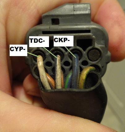 OBD1 Plug
5. Troubleshooting Common Issues During the Wiring Process
What are the common problems encountered when wiring an OBD1 distributor to an OBD2 harness, and how can they be resolved? Troubleshooting is a critical part of the wiring process. Common issues include incorrect wiring, poor connections, sensor failures, and ECU compatibility problems.
5.1 Common Wiring Problems and Solutions
- Incorrect Wiring: Double-check the wiring diagrams and pinout configurations to ensure all connections are correct.
- Poor Connections: Ensure all connections are secure and properly crimped. Use high-quality connectors and terminals.
- Grounding Issues: Verify that the distributor and ECU have a solid ground connection.
- Short Circuits: Inspect the wiring for any signs of damage or exposed wires that could cause a short circuit.
5.2 Addressing Sensor Failures
- CKP Sensor: Test the CKP sensor with a multimeter to ensure it is producing a valid signal.
- TDC Sensor: Verify that the TDC sensor is functioning correctly by checking its resistance and output voltage.
- CYP Sensor: Use an oscilloscope to monitor the CYP sensor signal and ensure it is within the specified range.
5.3 ECU Compatibility Issues
- Check ECU Compatibility: Ensure that the ECU is compatible with the OBD1 distributor and engine configuration.
- ECU Tuning: Adjust the ECU settings to properly recognize and interpret the signals from the OBD1 distributor.
- OBD2 Adapter: Consider using an OBD2 adapter to translate the OBD1 signals into a format compatible with the OBD2 system.
6. Advanced Techniques for Optimizing Engine Performance
What advanced techniques can be used to optimize engine performance after wiring an OBD1 distributor to an OBD2 harness? After successfully wiring the OBD1 distributor to the OBD2 harness, several advanced techniques can be used to optimize engine performance. These include ECU tuning, ignition timing adjustments, and fuel system modifications.
6.1 ECU Tuning for Enhanced Performance
- Custom Mapping: Create a custom fuel and ignition map tailored to the specific engine configuration.
- Real-Time Tuning: Use real-time tuning software to make adjustments while the engine is running.
- Dyno Tuning: Perform dyno tuning to optimize the engine’s performance under various load conditions.
6.2 Ignition Timing Adjustments
- Timing Light: Use a timing light to accurately adjust the ignition timing.
- Knock Sensor Monitoring: Monitor the knock sensor to detect and prevent engine knock.
- Advanced Timing Curves: Implement advanced timing curves to optimize performance across the RPM range.
6.3 Fuel System Modifications
- Upgraded Injectors: Install higher-flow fuel injectors to support increased power output.
- Fuel Pressure Regulator: Adjust the fuel pressure to optimize fuel delivery.
- Fuel Pump Upgrade: Upgrade the fuel pump to ensure a consistent and adequate fuel supply.
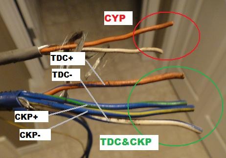 other end of wires
7. Safety Precautions to Take During the Wiring Process
What safety precautions should be observed during the wiring process? Safety should always be a top priority when working with electrical systems. Always disconnect the battery, use proper safety gear, and follow established safety procedures to prevent injury or damage.
7.1 Disconnecting the Battery
- Negative Terminal: Always disconnect the negative terminal of the battery before starting any wiring work.
- Wait Time: Wait at least 5 minutes after disconnecting the battery to allow the electrical system to fully discharge.
7.2 Using Proper Safety Gear
- Gloves: Wear insulated gloves to protect against electrical shock.
- Eye Protection: Use safety glasses or goggles to protect your eyes from debris.
- Protective Clothing: Wear appropriate clothing to protect your skin from contact with chemicals or sharp objects.
7.3 Following Safety Procedures
- Work Area: Ensure the work area is well-lit and free of clutter.
- Proper Tools: Use the correct tools for each task to avoid damage or injury.
- Double-Check: Always double-check your work before reconnecting the battery or starting the engine.
8. Case Studies of Successful OBD1 to OBD2 Distributor Conversions
Can you provide examples of successful OBD1 to OBD2 distributor conversions? Examining case studies of successful conversions can provide valuable insights and practical tips. These examples highlight the steps taken, challenges encountered, and solutions implemented by other enthusiasts and professionals.
8.1 Case Study 1: 1996 Honda Prelude with JDM H22A Engine
- Objective: Convert a 1996 Honda Prelude (OBD2) to run a JDM H22A engine (OBD1).
- Challenges: Integrating the OBD1 distributor with the OBD2 wiring harness and ECU.
- Solutions: Created a custom adapter harness to connect the OBD1 distributor to the OBD2 harness, and tuned the ECU to properly recognize the signals from the OBD1 distributor.
- Results: The engine ran smoothly with improved performance and no diagnostic trouble codes.
8.2 Case Study 2: 1998 Acura Integra with B18C1 Engine
- Objective: Install a B18C1 engine (OBD1) into a 1998 Acura Integra (OBD2).
- Challenges: Matching the distributor signals and ensuring proper engine timing.
- Solutions: Used a pre-made adapter harness designed for the B18C1 engine and verified the wiring connections with a multimeter and oscilloscope.
- Results: The engine started and ran without any issues, and the OBD2 system reported no error codes.
8.3 Case Study 3: 1994 Honda Civic with D16Z6 Engine
- Objective: Retrofit a D16Z6 engine (OBD1) into a 1994 Honda Civic (OBD2).
- Challenges: Adapting the distributor wiring and optimizing the fuel and ignition maps for the older engine.
- Solutions: Modified the OEM wiring harness to accommodate the OBD1 distributor, and tuned the ECU using a standalone engine management system.
- Results: The engine performed reliably with improved power and fuel efficiency.
9. Benefits of Upgrading to an OBD2 System
What are the advantages of upgrading to an OBD2 system? Upgrading to an OBD2 system offers several benefits, including enhanced diagnostic capabilities, improved emissions monitoring, and standardized data reporting. These advantages can lead to better vehicle performance, reduced repair costs, and compliance with environmental regulations.
9.1 Enhanced Diagnostic Capabilities
- Standardized Codes: OBD2 uses standardized diagnostic trouble codes (DTCs) that make it easier to identify and troubleshoot problems.
- Real-Time Data: OBD2 provides real-time data parameters that allow technicians to monitor engine performance and diagnose issues more accurately.
- Comprehensive Testing: OBD2 performs comprehensive testing of various engine components and systems, ensuring optimal performance and reliability.
9.2 Improved Emissions Monitoring
- Catalytic Converter Monitoring: OBD2 monitors the performance of the catalytic converter to ensure it is effectively reducing emissions.
- Oxygen Sensor Monitoring: OBD2 monitors the oxygen sensors to ensure proper air-fuel mixture and efficient combustion.
- Misfire Detection: OBD2 detects engine misfires that can lead to increased emissions and engine damage.
9.3 Standardized Data Reporting
- Universal Connector: OBD2 uses a universal 16-pin connector that allows for easy access to diagnostic data.
- Data Logging: OBD2 allows for data logging, which can be used to analyze engine performance and identify potential problems.
- Remote Diagnostics: OBD2 supports remote diagnostics, allowing technicians to diagnose and troubleshoot issues remotely.
10. Frequently Asked Questions (FAQ)
What are some common questions about wiring an OBD1 distributor to an OBD2 harness? Here are some frequently asked questions to provide additional guidance and clarity.
10.1 Is it possible to wire an OBD1 distributor to an OBD2 harness?
Yes, it is possible to wire an OBD1 distributor to an OBD2 harness, but it requires careful planning and execution. You need to identify the correct wires, create or purchase an adapter harness, and ensure that the ECU is compatible with the OBD1 distributor signals.
10.2 What tools are needed for this conversion?
The essential tools include:
- Multimeter
- Wiring diagrams
- Crimping tool
- Wire stripper
- Soldering iron
- Heat shrink tubing
- OBD2 scanner
10.3 How do I identify the correct wires on the OBD1 distributor and OBD2 harness?
Use wiring diagrams specific to your vehicle and engine combination. These diagrams provide a visual reference for identifying each wire and its corresponding function.
10.4 Can I use a pre-made adapter harness for this conversion?
Yes, using a pre-made adapter harness can simplify the wiring process and ensure proper connections. However, make sure the harness is specifically designed for your vehicle and engine combination.
10.5 What are the common issues that can occur during this conversion?
Common issues include incorrect wiring, poor connections, sensor failures, and ECU compatibility problems. Thoroughly test and verify each connection to prevent these issues.
10.6 How do I test the connections after wiring the OBD1 distributor to the OBD2 harness?
Use a multimeter to perform continuity and voltage tests on each connection. Start the engine and monitor for any error codes or performance issues. Use an OBD2 scanner to check for diagnostic trouble codes (DTCs).
10.7 Do I need to tune the ECU after this conversion?
Yes, it is often necessary to tune the ECU to properly recognize and interpret the signals from the OBD1 distributor. This may involve adjusting the fuel and ignition maps or using a standalone engine management system.
10.8 What safety precautions should I take during the wiring process?
Always disconnect the battery before starting any wiring work. Wear insulated gloves and safety glasses to protect against electrical shock and debris. Ensure the work area is well-lit and free of clutter.
10.9 Where can I find reliable wiring diagrams and pinout configurations?
Reliable sources include:
- Vehicle-specific repair manuals
- Online automotive forums and communities
- Professional wiring diagram databases
- Automotive service information websites
10.10 What are the benefits of upgrading to an OBD2 system?
The benefits include:
- Enhanced diagnostic capabilities
- Improved emissions monitoring
- Standardized data reporting
- Better vehicle performance
- Reduced repair costs
- Compliance with environmental regulations
By following this comprehensive guide and addressing these frequently asked questions, you can confidently and successfully wire an OBD1 distributor to an OBD2 harness.
Ready to take the next step?
Contact MERCEDES-DIAGNOSTIC-TOOL.EDU.VN today for expert advice and support on OBD1 to OBD2 conversions, diagnostic tools, and ECU tuning. Our team of experienced technicians is here to help you achieve optimal performance and reliability for your Mercedes-Benz.
Call us now at +1 (641) 206-8880 or visit our website at MERCEDES-DIAGNOSTIC-TOOL.EDU.VN. You can also visit us at 789 Oak Avenue, Miami, FL 33101, United States.
Let MERCEDES-DIAGNOSTIC-TOOL.EDU.VN be your trusted partner in automotive diagnostics and performance enhancements.
