Jeep Grand Cherokee 2006 Obd2 Codes are essential for diagnosing vehicle issues, and understanding these codes helps maintain optimal performance. At MERCEDES-DIAGNOSTIC-TOOL.EDU.VN, we provide in-depth knowledge and tools to help you diagnose and resolve these issues efficiently, ensuring your Jeep runs smoothly. With our guides, you will discover how to troubleshoot diagnostic trouble codes and use automotive diagnostic tools to address your car problems.
Contents
- 1. Understanding OBD2 Systems in Your 2006 Jeep Grand Cherokee
- 1.1 How OBD2 Systems Work
- 1.2 Accessing the OBD2 Connector
- 1.3 Scanning Tools: From Basic to Advanced
- 2. Decoding the Malfunction Indicator Lamp (MIL)
- 2.1 How the MIL Works
- 2.2 Reasons for MIL Illumination
- 2.3 Understanding One-Trip and Two-Trip Monitors
- 3. Dealing with MIL Illumination: What to Do?
- 3.1 Immediate Steps to Take
- 3.2 Risks of Prolonged Driving with the MIL On
- 3.3 Retrieving and Erasing Codes
- 4. Common Chrysler Diagnostic Trouble Codes (DTCs)
- 4.1 Understanding the Code Structure
- 4.2 Key to Understanding DTCs
- 4.3 Common DTCs and Their Meanings
1. Understanding OBD2 Systems in Your 2006 Jeep Grand Cherokee
OBD2 (On-Board Diagnostics II) systems are standard in vehicles manufactured after 1996, including the 2006 Jeep Grand Cherokee. These systems monitor various engine functions and diagnose problems or component failures, helping to minimize emissions. Let’s explore what you need to know.
1.1 How OBD2 Systems Work
OBD2 systems in the 2006 Jeep Grand Cherokee work by monitoring the performance of key components, including the engine, transmission, and emissions systems. When a problem is detected, the system generates a Diagnostic Trouble Code (DTC) and stores it in the vehicle’s computer.
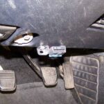
1.2 Accessing the OBD2 Connector
The OBD2 connector is typically located in the passenger compartment, accessible from the driver’s seat. In the Grand Cherokee WJ, you can find it under the dash, above the hood release lever. This connector allows you to plug in a scanning tool to read the stored DTCs.
1.3 Scanning Tools: From Basic to Advanced
Scanning tools range from simple handheld meters to sophisticated computer-based units. Basic tools provide a coded read-out of diagnostic functions, while advanced tools offer detailed analysis and troubleshooting steps. Recent advancements have made these tools more accessible to home mechanics and small shops.
2. Decoding the Malfunction Indicator Lamp (MIL)
The Malfunction Indicator Lamp (MIL), often called the “Check Engine” light, alerts the driver when the Powertrain Control Module (PCM) has recorded a DTC for an emissions-related circuit or component malfunction.
2.1 How the MIL Works
The MIL is controlled by a transistor on the instrument cluster circuit board, based on cluster programming and electronic messages received from the PCM. The bulb illuminates when provided a path to ground by the instrument cluster transistor.
2.2 Reasons for MIL Illumination
The MIL can turn on for several reasons:
- Bulb Test: When the ignition switch is turned to the On position, the MIL illuminates for about three seconds as a bulb test.
- MIL Lamp-On Message: When the cluster receives a MIL lamp-on message from the PCM, the indicator illuminates. It can flash or remain solid, as dictated by the PCM.
- Communications Error: If the cluster receives no lamp-on or lamp-off messages from the PCM for twenty consecutive seconds, the MIL is illuminated by the instrument cluster.
2.3 Understanding One-Trip and Two-Trip Monitors
Emissions systems often require multiple failed diagnostic tests before the PCM illuminates the MIL. These are known as ‘two-trip monitors.’ Tests that trigger the MIL after a single failure are called ‘one-trip monitors.’ A trip is defined as starting the vehicle and operating it to meet the criteria to run a given monitor.
3. Dealing with MIL Illumination: What to Do?
If the MIL illuminates, it’s essential to understand the potential issues and how to address them.
3.1 Immediate Steps to Take
Certain conditions, like a loose gas cap or poor fuel quality, may illuminate the light after starting the engine. If the light persists through several driving cycles, the vehicle should be serviced. In most cases, the vehicle will drive normally without requiring a tow.
3.2 Risks of Prolonged Driving with the MIL On
Driving for an extended period with the MIL on can cause further damage to the emission control system and affect fuel economy and driveability. The vehicle must be repaired before any emissions test. If the light flashes, severe catalytic converter damage and power loss can occur, requiring immediate service.
3.3 Retrieving and Erasing Codes
Retrieving codes can be done by turning the ignition key On/Off three times in succession, leaving it in the On position the fourth time. The digital odometer will display the codes. If no codes are present, “Done” will appear. Erasing codes can be done using a DRB III tool, which also erases all OBD II information, including warm-up cycles, trips, and Freeze Frame data.
4. Common Chrysler Diagnostic Trouble Codes (DTCs)
A Diagnostic Trouble Code indicates that the PCM has recognized an abnormal condition in the system. DTCs result from system or circuit failures but do not directly identify the failed component.
4.1 Understanding the Code Structure
A typical code structure is P0100, where:
- P = Powertrain
- 0 = Standard
- 1 = Emission Management
- 00 = Specific fault
4.2 Key to Understanding DTCs
- (M) Check Engine Lamp (MIL) will illuminate during engine operation if this Diagnostic Trouble Code was recorded.
- (G) Generator Lamp Illuminated – Chrysler uses ISO 9142-2 OBDII Communications Protocol
4.3 Common DTCs and Their Meanings
Here are some common DTCs for the 2006 Jeep Grand Cherokee:
| Scan Code | DRB Scan Tool Display | Description of Diagnostic Trouble Code |
|---|---|---|
| P0010 | A Camshaft Position Actuator Circuit (Bank 1) | |
| P0011 | A Camshaft Position – Timing Over-Advanced or System Performance (Bank 1)) | |
| P0012 | A Camshaft Position – Timing Over-Retarded (Bank 1) | |
| P0013 | B Camshaft Position – Actuator Circuit (Bank 1) | |
| P0014 | B Camshaft Position – Timing Over-Advanced or System Performance (Bank 1) | |
| P0015 | B Camshaft Position – Timing Over-Retarded (Bank 1) | |
| P0016 | Crankshaft/Camshaft Timing Misalignment | A rationality error has been detected for camshaft position out of phase with crankshaft. |
| P0020 | A Camshaft Position Actuator Circuit (Bank 2) | |
| P0021 | A Camshaft Position – Timing Over-Advanced or System Performance (Bank 2) | |
| P0022 | A Camshaft Position – Timing Over-Retarded (Bank 2) | |
| P0023 | B Camshaft Position – Actuator Circuit (Bank 2) | |
| P0024 | B Camshaft Position – Timing Over-Advanced or System Performance (Bank 2) | |
| P0025 | B Camshaft Position – Timing Over-Retarded (Bank 2) | |
| P0030 | 02 Sensor Heater Control Circuit (Bank 1 Sensor 1) | Shorted condition detected in the oxygen sensor heater element control feedback sense circuit. |
| P0031 | 02 Sensor Heater Control Circuit Low (Bank 1 Sensor 1) | Shorted low condition detected in the oxygen sensor 1/1 heater elementcontrol feedback sense circuit |
| P0032 | 02 Sensor Heater Control Circuit High (Bank 1 Sensor 1) | Shorted high condition detected in the oxygen sensor 1/1 heater element control feedback sense circuit |
| P0033 | Turbo Charger Bypass Valve Control Circuit | |
| P0034 | Turbo Charger Bypass Valve Control Circuit Low | |
| P0035 | Turbo Charger Bypass Valve Control Circuit High | |
| P0036 | 02 Sensor Heater Control Circuit (Bank 1 Sensor 2) | Shorted condition detected in the oxygen sensor heater element control feedback sense circuit. |
| P0037 | 02 Sensor Heater Control Circuit Low (Bank 1 Sensor 2) | Shorted condition detected in the oxygen sensor heater element control feedback sense circuit. |
| P0038 | 02 Sensor Heater Control Circuit High (Bank 1 Sensor 2) | Shorted condition detected in the oxygen sensor heater element control feedback sense circuit. |
| P0042 | 02 Sensor Heater Control Circuit (Bank 1 Sensor 3) | Shorted condition detected in the oxygen sensor heater element control feedback sense circuit. |
| P0043 | 02 Sensor Heater Control Circuit Low (Bank 1 Sensor 3) | Shorted condition detected in the oxygen sensor heater element control feedback sense circuit. |
| P0044 | 02 Sensor Heater Control Circuit High (Bank 1 Sensor 3) | Shorted condition detected in the oxygen sensor heater element control feedback sense circuit. |
| P0050 | 02 Sensor Heater Control Circuit (Bank 2 Sensor 1) | Shorted condition detected in the oxygen sensor heater element control feedback sense circuit. |
| P0051 | 02 Sensor Heater Control Circuit Low (Bank 2 Sensor 1) | Shorted condition detected in the oxygen sensor heater element control feedback sense circuit. |
| P0052 | 02 Sensor Heater Control Circuit High (Bank 2 Sensor 1) | Shorted condition detected in the oxygen sensor heater element control feedback sense circuit. |
| P0056 | 02 Sensor Heater Control Circuit (Bank 2 Sensor 2) | Shorted condition detected in the oxygen sensor heater element control feedback sense circuit. |
| P0057 | 02 Sensor Heater Control Circuit Low (Bank 2 Sensor 2) | Shorted condition detected in the oxygen sensor heater element control feedback sense circuit. |
| P0058 | 02 Sensor Heater Control Circuit High (Bank 2 Sensor 2) | Shorted condition detected in the oxygen sensor heater element control feedback sense circuit. |
| P0062 | 02 Sensor Heater Control Circuit High (Bank 2 Sensor 2) | Shorted condition detected in the oxygen sensor heater element control feedback sense circuit. |
| P0063 | HO2S Heater Control Circuit Low (Bank 2 Sensor 3) | Shorted condition detected in the oxygen sensor heater element control feedback sense circuit. |
| P0064 | HO2S Heater Control Circuit High (Bank 2 Sensor 3) | Shorted condition detected in the oxygen sensor heater element control feedback sense circuit. |
| P0065 | Air Assisted Injector Control Range/Performance | |
| P0066 | Air Assisted Injector Control Circuit or Circuit Low | |
| P0067 | Air Assisted Injector Control Circuit High | |
| P0068 | Manifold Pressure/Throttle Position | Correlation MAP sensor signal does not correlate to throttle position sensor signal. Possible vacuum leak. |
| P0070 | Ambient Temp Sensor Stuck | A rationality error has been detected in the ambient temperature sensor test. |
| P0071 (M) | Ambient Temp Sensor Performance | Ambient change less than 3° C in 200 miles. |
| P0072 | Ambient Temp Sensor Low Input | Ambient temperature sensor input below the minimum acceptable voltage. |
| P0073 | Ambient Temp Sensor High Input | Ambient temperature sensor input above the maximum acceptable voltage. |
| P0074 | Ambient Air Temperature Sensor Circuit Intermittent | |
| P0075 | Intake Valve Control Solenoid Circuit (Bank 1) | |
| P0076 | Intake Valve Control Solenoid Circuit Low (Bank 1) | |
| P0077 | Intake Valve Control Solenoid Circuit High (Bank 1) | |
| P0078 | Exhaust Valve Control Solenoid Circuit (Bank 1) | |
| P0079 | Exhaust Valve Control Solenoid Circuit Low (Bank 1) | |
| P0080 | Exhaust Valve Control Solenoid Circuit High (Bank 1) | |
| P0081 | Intake valve Control Solenoid Circuit (Bank 2) | |
| P0082 | Intake Valve Control Solenoid Circuit Low (Bank 2) | |
| P0083 | Intake Valve Control Solenoid Circuit High (Bank 2) | |
| P0084 | Exhaust Valve Control Solenoid Circuit (Bank 2) | |
| P0085 | Exhaust Valve Control Solenoid Circuit Low (Bank 2) | |
| P0086 | Exhaust Valve Control Solenoid Circuit High (Bank 2) | |
| P0100 | Mass or Volume Air Flow Circuit | |
| P0101 | Mass or Volume Air Flow Circuit Range/Performance Problem | |
| P0102 | Mass or Volume Air Flow Circuit Low Input | |
| P0103 | Mass or Volume Air Flow Circuit High Input | |
| P0104 | Mass or Volume Air Flow Circuit Intermittent | |
| P0105 | Manifold Absolute Pressure/Barometric Pressure Circuit | |
| P0106 (M) | Manifold Absolute Pressure/Barometric Pressure Circuit Range/Performance Problem | MAP sensor input voltage out of an acceptable range detected during reading of barometric pressure at key-on. |
| P0107 (M) | Manifold Absolute Pressure/Barometric Pressure Circuit Low Input | MAP sensor input below minimum acceptable voltage. |
| P0108 (M) | Manifold Absolute Pressure/Barometric Pressure Circuit High Input | MAP sensor input above maximum acceptable voltage. |
| P0109 | Manifold Absolute Pressure/Barometric Pressure Circuit Intermittent | |
| P0110 | Intake Air Temp Sensor Stuck | A rationality error has been detected for the intake air temperature sensor. |
| P0111 (M) | Intake Air Temperature Circuit Range/Performance Problem | Air change less than 3° C in 200 miles. |
| P0112 (M) | Intake Air Temperature Circuit Low Input | Intake air (charge) temperature sensor input below the minimum acceptable voltage. |
| P0113 (M) | Intake Air Temperature Circuit High Input | Intake air (charge) temperature sensor input above the maximum acceptable voltage. |
| P0114 | Intake Air Temperature Circuit Intermittent | |
| P0115 | Engine Coolant Temperature Circuit | |
| P0116 | Engine Coolant Temperature Circuit Range/Performance Problem | A rationality error has been detected in the coolant temperature sensor. |
| P0117 (M) | Engine Coolant Temperature Circuit Low Input | Engine coolant temperature sensor input below the minimum acceptable voltage. |
| P0118 (M) | Engine Coolant Temperature Circuit High Input | Engine coolant temperature sensor input above the maximum acceptable voltage. |
| P0119 | Engine Coolant Temperature Circuit Intermittent | Engine coolant temperature sensor input above the maximum acceptable voltage. |
| P0120 | Throttle/Pedal Position Sensor/Switch A Circuit | Engine coolant temperature sensor input above the maximum acceptable voltage. |
| P0121 (M) | Throttle/Pedal Position Sensor/Switch A Circuit Range/Performance Problem | TPS signal does not correlate to MAP sensor signal. |
| P0121 (M) | Accelerator Position Sensor (APPS) | APPS voltage input below the minimum acceptable voltage. |
| P0122 (M) | Throttle/Pedal Position Sensor/Switch A Circuit Low Input | Throttle position sensor input below the acceptable voltage range. |
| P0122 (M) | Accelerator Position Sensor (APPS) Signal Voltage Too Low | APPS voltage input below the minimum acceptable voltage. |
| P0123 (M) | Throttle/Pedal Position Sensor/Switch A Circuit Intermittent | Throttle position sensor input above the maximum acceptable voltage. Follow all appropriate diagnostics for the fault that is present. Prior to replacing parts, check all connectors between the speed control switch and the PCM for moisture Internally the PCM uses the same A/D (analog to digital) converter for TPS voltage as it does for the speed control switch sense. If the v-37 circuit has voltage bleed over from another source, a code of TPS Shorted to voltage may be set in the PCM. The DN model equipped with rear heat option, has an external water pump to circulate coolant to the rear heater. If you find coolant in the bulkhead connector, the likely cause would be a leaking coolant pump. Pump should be replaced if found leaking. If the code sets when the A/C is turned on go right to the bulk head connector and check for moisture. Check for a shorted clock spring causing the speed control 5 volt feed to be shorted to power. |
| P0123 (M) | Accelerator Position Sensor (APPS) Signal Voltage Too High | APPS voltage input above the maximum acceptable voltage. |
| P0125 (M) | Insufficient Coolant Temperature for Closed Loop Fuel Control | Time to enter Closed Loop Operation (Fuel Control) is excessive. |
| P0125 (M) | Engine is Cold Too Long | Engine does not reach operating temperature. |
| P0126 | Insufficient Coolant Temperature for Stable Operation | |
| P0127 | Intake Air Temperature Too High | |
| P0128 | Coolant Thermostat (Coolant Temperature Below Thermostat Regulating Temperature) | A rationality error has been detected for the thermostat. |
| P0129 | Barometic Pressure Out-of-Range low | MAP sensor input voltage out of an acceptable range detected during reading of barometric pressure. |
| P0130 | O2 Sensor Circuit (Bank 1 Sensor 1) | An open or shorted condition detected in the ASD or CNG shutoff relay control ckt. |
| P0131 (M) | O2 Sensor Circuit Low Voltage (Bank 1 Sensor 1) | Oxygen sensor input voltage maintained below normal operating range. |
| P0132 (M) | O2 Sensor Circuit High Voltage (Bank 1 Sensor 1) | Oxygen sensor input voltage maintained above normal operating range. |
| P0133 (M) | O2 Sensor Circuit Slow Response (Bank 1 Sensor 1) | Oxygen sensor response slower than minimum required switching frequency. |
| P0134 (M) | O2 Sensor Circuit No Activity Detected (Bank 1 Sensor 1) | Neither rich or lean condition is detected from the oxygen sensor input. |
| P0135 (M) | O2 Sensor Heater Circuit (Bank 1 Sensor 1) | Oxygen sensor heater element malfunction. |
| P0136 | O2 Sensor Circuit Malfunction (Bank 1 Sensor 2) | An open or shorted condition detected in the ASD or CNG shutoff relay control ckt. |
| P0137 (M) | O2 Sensor Circuit Low Voltage (Bank 1 Sensor 2) | Oxygen sensor input voltage maintained below normal operating range. |
| P0138 (M) | O2 Sensor Circuit High Voltage (Bank 1 Sensor 2) | Oxygen sensor input voltage maintained above normal operating range. |
| P0139 (M) | OS Sensor Circuit Slow Response (Bank 1 Sensor 2) | Oxygen sensor response not as expected. |
| P0140 (M) | O2 Sensor Circuit No Activity Detected (Bank 1 Sensor 2) | Neither rich or lean condition is detected from the oxygen sensor. |
| P0141 (M) | O2 Sensor Heater Circuit (Bank 1 Sensor 2) | Oxygen sensor heater element malfunction. O2 sensor voltage greater than 3 volts for 60 to 240 seconds. |
| P0142 (M) | Sensor Circuit Malfunction (Bank 1 Sensor 3) | Oxygen sensor heater element malfunction. |
| P0143 | O2 Sensor Circuit Low Voltage (Bank 1 Sensor 3) | Oxygen sensor input voltage maintained below normal operating range. |
| P0144 | O2 Sensor Circuit High Voltage (Bank 1 Sensor 3) | Oxygen sensor input voltage maintained above normal operating range. |
| P0145 | O2 Sensor Circuit Slow Response (Bank 1 Sensor 3) | Oxygen sensor response slower than minimum required switching frequency. |
| P0146 | O2 Sensor Circuit No Activity Detected (Bank 1 Sensor 3) | Neither rich or lean condition is detected from the oxygen sensor. |
| P0147 | O2 Sensor Heater Circuit (Bank 1 Sensor 3) | Oxygen sensor heater element malfunction. |
| P0148 | Fuel Delivery Error | |
| P0149 | Fuel Timing Error | |
| P0150 | O2 Sensor Circuit (Bank 2 Sensor 1) | |
| P0151 (M) | O2 Sensor Circuit Low Voltage (Bank 2 Sensor 1) | Oxygen sensor input voltage maintained below normal operating range. |
| P0152 (M) | O2 Sensor Circuit High Voltage (Bank 2 Sensor 1) | Oxygen sensor input voltage sustained above normal operating range. |
| P0153 (M) | O2 Sensor Circuit Slow Response (Bank 2 Sensor 1) | Oxygen sensor response slower than minimum required switching frequency. |
| P0154 (M) | O2 Sensor Circuit No Activity Detected (Bank 2 Sensor 1) | Neither rich or lean condition is detected from the oxygen sensor. |
| P0155 (M) | O2 Sensor Heater Circuit (Bank 2 Sensor 1) | Oxygen sensor heater element malfunction. |
| P0156 (M) | O2 Sensor Circuit Malfunction (Bank 2 Sensor2) | Oxygen sensor heater element malfunction. |
| P0157 (M) | O2 Sensor Circuit Low Voltage (Bank 2 Sensor 2) | Oxygen sensor input voltage maintained below normal operating range. |
| P0158 (M) | O2 Sensor Circuit High Voltage (Bank 2 Sensor 2) | Oxygen sensor input voltage maintained above normal operating range. |
| P0159 | O2 Sensor Circuit Slow Response (Bank 2 Sensor 2) | Oxygen sensor response slower than minimum required switching frequency. |
| P0160 (M) | O2 Sensor Circuit No Activity Detected (Bank 2 Sensor 2) | Neither rich or lean condition is detected from the oxygen sensor. |
| P0161 (M) | O2 Sensor Heater Circuit (Bank 2 Sensor 2) | Oxygen sensor heater element malfunction. O2 sensor voltage greater than 3 volts for 60 to 240 seconds. |
| P0162 (M) | O2 Sensor Circuit Malfunction (Bank 2 Sensor 3) | Oxygen sensor heater element malfunction. |
| P0163 (M) | O2 Sensor Circuit Low Voltage (Bank 2 Sensor 3) | |
| P0164 (M) | O2 Sensor Circuit High Voltage (Bank 2 Sensor3) | |
| P0165 | O2 Sensor Circuit Slow Response (Bank 2 Sensor 3) | |
| P0166 | O2 Sensor Circuit No Activity Detected (Bank 2 Sensor 3) | |
| P0167 | OS Sensor Heater Circuit (Bank 2 Sensor 3) | |
| P0168 | Fuel Temperature Too High | |
| P0169 | Incorrect Fuel Composition | |
| P0170 | Fuel Trim (Bank 1) | |
| P0171 (M) | System too Lean (Bank 1) | A lean air/fuel mixture has been indicated by an abnormally rich correction factor. |
| P0172 (M) | System too Rich (Bank 1) | A rich air/fuel mixture has been indicated by an abnormally lean correction factor. Was the fuel pressure checked with a DRBIII pressure transducer? Is the fuel pressure within specification with engine running at normal operating temperature? Verify the correct DRBIII PEP module pressure transducer is being used It is critical when reading pressures with the DRBIII PEP module pressure transducers that the proper transducer is being used. A too high of value transducer will cause inaccurate readings. It is also critical that the DRBIII and pressure transducer is zeroed out before taking a reading.Repair or replace any fuel system malfunctioning components. |
| P0173 (M) | Fuel Trim Malfunction (Bank 2) | |
| P0174 (M) | System too Lean (Bank 2) | A lean air/fuel mixture has been indicated by an abnormally rich correction factor. |
| P0175 (M) | System too Rich (Bank 2) | A rich air/fuel mixture has been indicated by an abnormally lean correction factor. |
| P0176 | Fuel Composition Sensor Circuit | No calibration voltage present from flex fuel sensor. |
| P0177 | Fuel Composition Sensor Circuit Range/Performance | |
| P0178 | Fuel Composition Sensor Circuit Low Input | Flex fuel sensor input below minimum acceptable voltage. |
| P0178 | Water in Fuel Light—Water In Fuel Sensor Voltage Too Low | Loss of water-in-fuel circuit or sensor. |
| P0179 | Fuel Composition Sensor Circuit High Input | Flex fuel sensor input above maximum acceptable voltage. |
| P0180 | Fuel Temperature Sensor A Circuit | |
| P0181 | Fuel Temperature Sensor A Circuit Range/Performance | |
| P0182 (M) | Fuel Temperature Sensor A Circuit Low Input | Compressed natural gas temperature sensor voltage below acceptable voltage |
| P0183 (M) | Fuel Temperature Sensor A Circuit High Input | Compressed natural gas temperature sensor voltage above acceptable voltage |
| P0184 | Fuel Temperature Sensor A Circuit Intermittent | |
| P0185 | Fuel Temperature Sensor B Circuit | |
| P0186 | Fuel Temperature Sensor B Circuit Range/Performance | |
| P0187 | Fuel Temperature Sensor B Circuit Low Input | |
| P0188 | Fuel Temperature Sensor B Circuit High Input | |
| P0189 | Fuel Temperature Sensor B Circuit Intermittent | |
| P0190 | Fuel Rail Pressure Sensor Circuit | |
| P0191 | Fuel Rail Pressure Sensor Circuit Range/Performance | |
| P0192 | Fuel Rail Pressure Sensor Circuit Low Input | |
| P0193 | Fuel Rail Pressure Sensor Circuit High Input | |
| P0194 | Fuel Rail Pressure Sensor Circuit Intermittent | |
| P0195 | Engine Oil Temperature Sensor | |
| P0196 | Engine Oil Temperature Sensor Range/Performance | |
| P0197 | Engine Oil Temperature Sensor Low | |
| P0198 | Engine Oil Temperature Sensor High | |
| P0199 | Engine Oil Temperature Sensor Intermittent | |
| P0200 | Injector Circuit | |
| P0201 (M) | Injector # 1 Control Circuit | An open or shorted condition detected in control circuit for Injector # 1 or the INJ 1 injector bank. |
| P0202 (M) | Injector # 2 Control Circuit | An open or shorted condition detected in control circuit for Injector # 2 or the INJ 2 injector bank. |
| P0203 (M) | Injector # 3 Control Circuit | An open or shorted condition detected in control circuit for Injector # 3 or the INJ 3 injector bank. |
| P0204 (M) | Injector # 4 Control Circuit | Injector # 4 or INJ 4 injector bank output driver stage does not respond properly to the control signal. |
| P0205 (M) | Injector # 5 Control Circuit | Injector # 5 output driver stage does not respond properly to the control signal. |
| P0206 (M) | Injector # 6 Control Circuit | Injector # 6 output driver stage does not respond properly to the control signal. |
| P0207 (M) | Injector # 7 Control Circuit | Injector # 7 output driver stage does not respond properly to the control signal. |
| P0208 (M) | Injector # 8 Control Circuit | Injector # 8 output driver stage does not respond properly to the control signal. |
| P0209 (M) | Injector # 9 Control Circuit | Injector # 9 output driver stage does not respond properly to the control signal. |
| P0210 (M) | Injector |