Are you looking to enhance your Mercedes-Benz diagnostics with the power of open-source technology? With an Arduino Obd2 Sparkfun setup, you can unlock a world of real-time data and customization. At MERCEDES-DIAGNOSTIC-TOOL.EDU.VN, we provide comprehensive guides and support to help you leverage this powerful combination for diagnosing and monitoring your vehicle’s performance. Unlock your Mercedes’ potential with custom diagnostics and data insights.
Contents
- 1. Understanding Arduino OBD2 Sparkfun for Mercedes Diagnostics
- 1.1. What is Arduino OBD2 Sparkfun?
- 1.2. Why Use Arduino OBD2 Sparkfun for Mercedes?
- 1.3. Key Components Required
- 1.4. Exploring the Technical Specifications
- 2. Setting Up Your Arduino OBD2 Sparkfun System
- 2.1. Connecting the Hardware
- 2.2. Installing Necessary Libraries
- 2.3. Writing the Arduino Code
- 2.4. Uploading the Code to Arduino
- 3. Reading and Interpreting Data
- 3.1. Understanding OBD2 PIDs
- 3.2. Parsing OBD2 Responses
- 3.3. Displaying Data on LCD
- 3.4. Best Practices for Data Interpretation
- 4. Advanced Applications and Customization
- 4.1. Data Logging
- 4.2. Custom Gauges and Displays
- 4.3. Real-Time Monitoring and Alerts
- 4.4. Integrating GPS Data
- 4.5. Creating a Head-Up Display (HUD)
- 5. Troubleshooting Common Issues
- 5.1. No Data Received
- 5.2. Incorrect Data
- 5.3. Communication Errors
- 5.4. Addressing Protocol Incompatibilities
- 5.5. Ensuring Power Stability
- 6. Safety Precautions
- 6.1. Electrical Safety
- 6.2. Data Security
- 6.3. Vehicle Operation
- 6.4. Handling CAN Bus Interference
- 6.5. Ensuring Compliance with Standards
- 7. Benefits of Using MERCEDES-DIAGNOSTIC-TOOL.EDU.VN
- 7.1. Expert Guidance
- 7.2. Comprehensive Resources
- 7.3. Community Support
- 7.4. Custom Solutions
- 7.5. Up-to-Date Information
- 8. Real-World Applications
- 8.1. Performance Monitoring
- 8.2. Fuel Efficiency Analysis
- 8.3. Diagnostics and Troubleshooting
- 8.4. Fleet Management
- 8.5. Enhancing Vehicle Security
- 9. The Future of Arduino OBD2 in Automotive Diagnostics
- 9.1. Integration with AI and Machine Learning
- 9.2. Wireless Connectivity and Cloud Integration
- 9.3. Enhanced Customization and Personalization
- 9.4. Predictive Maintenance
- 9.5. Autonomous Driving Support
- 10. Frequently Asked Questions (FAQ)
1. Understanding Arduino OBD2 Sparkfun for Mercedes Diagnostics
1.1. What is Arduino OBD2 Sparkfun?
Arduino OBD2 Sparkfun refers to the integration of an Arduino microcontroller with an OBD2 (On-Board Diagnostics II) interface using components from Sparkfun Electronics. The OBD2 port in your Mercedes-Benz provides access to a wealth of data about the vehicle’s operation, including engine RPM, vehicle speed, coolant temperature, and oxygen sensor readings. The Arduino acts as a programmable interface to read this data, while Sparkfun provides the necessary hardware and libraries to simplify the connection and data interpretation. This combination allows you to create custom diagnostic tools, data loggers, and performance monitors tailored to your specific needs.
1.2. Why Use Arduino OBD2 Sparkfun for Mercedes?
Using an Arduino OBD2 Sparkfun setup for your Mercedes-Benz offers several advantages:
- Customization: You can tailor the system to display only the data you need, in the format you prefer.
- Cost-Effectiveness: Compared to professional diagnostic tools, an Arduino-based system can be significantly cheaper.
- Educational Value: Building and programming the system provides a deeper understanding of your vehicle’s inner workings.
- Open Source: The open-source nature of Arduino allows for community-driven development and readily available code examples.
- Expandability: You can add sensors and functionalities to the system, such as GPS logging or custom alerts.
1.3. Key Components Required
To build an Arduino OBD2 Sparkfun system, you will need the following components:
- Arduino Board: An Arduino Uno or Nano is a popular choice due to its ease of use and wide availability.
- Sparkfun OBD-II UART Board: This board provides the physical interface to the OBD2 port and handles the serial communication with the Arduino.
- OBD2 Cable: A standard OBD2 cable to connect the Sparkfun board to your Mercedes’ OBD2 port.
- Display (Optional): An LCD screen or other display to visualize the data.
- Jumper Wires: To connect the components together.
- USB Cable: To program the Arduino.
1.4. Exploring the Technical Specifications
The technical specifications are crucial for a successful Arduino OBD2 Sparkfun integration. The OBD-II UART board typically communicates via serial UART, requiring the Arduino to be configured accordingly. Data is transmitted using standard OBD-II PID (Parameter Identification) codes. The Arduino code must send the appropriate PID codes and correctly interpret the responses. The Sparkfun OBD-II UART board supports standard OBD-II protocols, including CAN (Controller Area Network), which is commonly used in Mercedes-Benz vehicles.
Here’s a table summarizing key technical aspects:
| Aspect | Details |
|---|---|
| Communication | Serial UART |
| Protocols Supported | CAN, ISO 9141-2, KWP2000 |
| Baud Rate | 9600 bps (default), configurable |
| PID Codes | Standard OBD-II PIDs (e.g., 010C for RPM, 010D for Speed) |
| Voltage | 5V (Arduino), 12V (OBD-II Port) |
| Operating Temperature | -40°C to 85°C (typical for automotive components) |
Understanding these specifications will help in troubleshooting and optimizing the system for reliable data acquisition.
2. Setting Up Your Arduino OBD2 Sparkfun System
2.1. Connecting the Hardware
The hardware setup involves connecting the Sparkfun OBD-II UART board to the Arduino. Here’s a step-by-step guide:
- Connect Power: Connect the 5V and GND pins from the Arduino to the corresponding pins on the Sparkfun OBD-II UART board.
- Connect Serial Communication: Connect the TX (transmit) pin from the Sparkfun board to the RX (receive) pin on the Arduino, and the RX pin from the Sparkfun board to the TX pin on the Arduino.
- Connect to OBD2 Port: Plug the OBD2 cable into your Mercedes’ OBD2 port and connect the other end to the Sparkfun board.
- Connect Display (Optional): If you are using a display, connect it to the appropriate pins on the Arduino according to the display’s documentation.
 Arduino OBD2 Connection Diagram
2.2. Installing Necessary Libraries
To simplify the communication with the OBD2 port, you’ll need to install the following libraries in the Arduino IDE:
- OBD2 Library: This library provides functions for sending OBD2 commands and parsing the responses. You can find several OBD2 libraries available in the Arduino Library Manager.
- SoftwareSerial Library: If you are using a different set of pins for serial communication, you’ll need the SoftwareSerial library to create a software serial port. This library is usually included with the Arduino IDE.
- Display Library (Optional): If you are using a display, install the appropriate library for your display type (e.g., LiquidCrystal for LCDs).
2.3. Writing the Arduino Code
The Arduino code is responsible for initializing the serial communication, sending OBD2 commands, and displaying the data. Here’s a basic example:
#include <SoftwareSerial.h>
#include <OBD2.h> // Make sure you have an OBD2 library installed

SoftwareSerial obdSerial(2, 3); // RX, TX pins for OBD2 communication

void setup() {
  Serial.begin(9600);
  obdSerial.begin(9600);
  delay(1000);

  Serial.println("Initializing OBD2...");
  obdSerial.println("ATZ"); // Reset OBD2 adapter
  delay(1000);
  obdSerial.println("ATE0"); // Disable echo
  delay(1000);
  obdSerial.println("ATL0"); // Set linefeed off
  delay(1000);
  obdSerial.println("ATH0"); // Set headers off
  delay(1000);
}

void loop() {
  // Request RPM
  obdSerial.println("010C");
  String rpmResponse = getOBDResponse();
  if (rpmResponse.length() > 0) {
    int rpm = parseRPM(rpmResponse);
    Serial.print("RPM: ");
    Serial.println(rpm);
  }

  // Request Speed
  obdSerial.println("010D");
  String speedResponse = getOBDResponse();
  if (speedResponse.length() > 0) {
    int speed = parseSpeed(speedResponse);
    Serial.print("Speed: ");
    Serial.println(speed);
  }

  delay(1000);
}

String getOBDResponse() {
  String response = "";
  while (obdSerial.available() > 0) {
    char c = obdSerial.read();
    response += c;
  }
  return response;
}

int parseRPM(String response) {
  // Parse the RPM from the OBD2 response
  // This will depend on the specific format of the response
  // Example: "41 0C 0B FF"
  // You'll need to extract the relevant part and convert it to an integer
  // Consult the OBD2 documentation for your vehicle to understand the format
  return 0; // Replace with your parsing logic
}

int parseSpeed(String response) {
  // Parse the Speed from the OBD2 response
  // This will depend on the specific format of the response
  // Example: "41 0D 30"
  // You'll need to extract the relevant part and convert it to an integer
  // Consult the OBD2 documentation for your vehicle to understand the format
  return 0; // Replace with your parsing logic
}
This code initializes the serial communication with the OBD2 adapter, sends requests for RPM and speed, and prints the responses to the serial monitor. You’ll need to implement the parseRPM and parseSpeed functions to extract the actual data from the OBD2 responses.
2.4. Uploading the Code to Arduino
- Connect Arduino: Connect your Arduino board to your computer using a USB cable.
- Select Board and Port: In the Arduino IDE, select the correct board type (e.g., Arduino Uno) and the port to which your Arduino is connected.
- Upload Code: Click the “Upload” button to compile and upload the code to your Arduino.
- Monitor Output: Open the Serial Monitor in the Arduino IDE to see the data being received from the OBD2 port.
3. Reading and Interpreting Data
3.1. Understanding OBD2 PIDs
OBD2 PIDs (Parameter Identification) are codes used to request specific data from the vehicle’s ECU (Engine Control Unit). Each PID corresponds to a particular sensor or parameter. Some common PIDs include:
- 010C: Engine RPM
- 010D: Vehicle Speed
- 0105: Coolant Temperature
- 010F: Intake Air Temperature
- 0110: Mass Air Flow (MAF) Rate
- 0104: Calculated Load Value
Consult the OBD2 documentation for your specific Mercedes model to find the PIDs supported by your vehicle.
3.2. Parsing OBD2 Responses
The OBD2 responses are typically in hexadecimal format and require parsing to extract the actual data. The format of the response depends on the PID being requested. Here’s an example of how to parse the RPM response:
int parseRPM(String response) {
  // Example response: "41 0C 0B FF"
  // Remove the first two bytes (41 0C)
  response = response.substring(6);
  // Convert the remaining hexadecimal value to an integer
  long rpmHex = strtol(response.c_str(), NULL, 16);
  // Divide by 4 to get the actual RPM
  int rpm = rpmHex / 4;
  return rpm;
}
This function extracts the hexadecimal value from the response, converts it to an integer, and divides by 4 to get the actual RPM value.
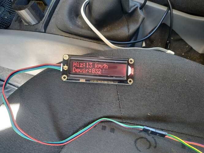
3.3. Displaying Data on LCD
If you are using an LCD screen, you can display the data using the LiquidCrystal library. Here’s an example:
#include <LiquidCrystal.h>

// Define LCD pins
const int rs = 12, en = 11, d4 = 5, d5 = 4, d6 = 3, d7 = 2;
LiquidCrystal lcd(rs, en, d4, d5, d6, d7);

void setup() {
  lcd.begin(16, 2); // Initialize LCD with 16 columns and 2 rows
}

void loop() {
  // Get RPM and Speed data
  int rpm = getRPM();
  int speed = getSpeed();

  // Display data on LCD
  lcd.setCursor(0, 0);
  lcd.print("RPM: ");
  lcd.print(rpm);

  lcd.setCursor(0, 1);
  lcd.print("Speed: ");
  lcd.print(speed);

  delay(1000);
}
This code initializes the LCD, retrieves the RPM and speed data, and displays it on the LCD screen.
3.4. Best Practices for Data Interpretation
Interpreting data correctly is crucial. Here are some best practices:
- Cross-Reference Data: Compare the data with known specifications for your Mercedes model.
- Understand Units: Ensure you understand the units of measurement for each PID.
- Use Reliable Libraries: Rely on well-tested and reliable OBD-II libraries.
- Calibrate Sensors: If possible, calibrate the sensors to improve accuracy.
- Monitor Trends: Look for trends in the data over time to identify potential issues.
For example, consistently high coolant temperatures may indicate a cooling system problem, while erratic MAF readings could suggest a faulty mass airflow sensor.
4. Advanced Applications and Customization
4.1. Data Logging
You can log the data to an SD card for later analysis. This requires an SD card module and the SD library. Here’s a basic example:
#include <SD.h>

File dataFile;

void setup() {
  SD.begin(4); // Initialize SD card
  dataFile = SD.open("data.txt", FILE_WRITE);
  dataFile.println("Time,RPM,Speed"); // Write header
  dataFile.close();
}

void loop() {
  // Get RPM and Speed data
  int rpm = getRPM();
  int speed = getSpeed();

  // Log data to SD card
  dataFile = SD.open("data.txt", FILE_WRITE);
  dataFile.print(millis());
  dataFile.print(",");
  dataFile.print(rpm);
  dataFile.print(",");
  dataFile.println(speed);
  dataFile.close();

  delay(1000);
}
This code logs the RPM and speed data to a file named “data.txt” on the SD card.
4.2. Custom Gauges and Displays
You can create custom gauges and displays using various display technologies, such as OLED screens or TFT displays. These displays offer more flexibility in terms of layout and visual appeal.
4.3. Real-Time Monitoring and Alerts
You can set up real-time monitoring and alerts based on specific data thresholds. For example, you can trigger an alert if the coolant temperature exceeds a certain limit or if the engine RPM is too high.
4.4. Integrating GPS Data
Adding GPS functionality can provide location-based diagnostics. By combining OBD-II data with GPS coordinates, you can analyze vehicle performance in different geographic locations. This requires a GPS module and integrating its data with the Arduino.
Here’s a simple example of how GPS data can be incorporated:
#include <TinyGPS++.h>
#include <SoftwareSerial.h>

SoftwareSerial ss(4, 3); // RX, TX pins for GPS

TinyGPSPlus gps;

void setup() {
  Serial.begin(9600);
  ss.begin(9600);
}

void loop() {
  while (ss.available() > 0) {
    gps.encode(ss.read());
  }

  if (gps.location.isUpdated()) {
    Serial.print("Latitude= ");
    Serial.print(gps.location.lat(), 6);
    Serial.print(" Longitude= ");
    Serial.print(gps.location.lng(), 6);
    Serial.println();
  }
}
By merging this GPS data with OBD-II data, you can create comprehensive performance logs that include location, speed, RPM, and other parameters.
4.5. Creating a Head-Up Display (HUD)
A more advanced project involves creating a head-up display (HUD) that projects real-time data onto the windshield. This requires a transparent display and a projector to overlay the data onto the driver’s line of sight.
Here’s how you could structure the code for a basic HUD:
// This is a conceptual example and requires specific hardware
void displayHUDData(int rpm, int speed) {
  // Code to project RPM and Speed onto the windshield
  // This typically involves controlling a small projector or transparent display
  // and overlaying the data onto the driver's line of sight
  Serial.print("Projecting RPM: ");
  Serial.print(rpm);
  Serial.print(" and Speed: ");
  Serial.println(speed);
}

void loop() {
  int rpm = getRPM();
  int speed = getSpeed();

  displayHUDData(rpm, speed);
  delay(100);
}
Creating a fully functional HUD requires careful calibration and integration with the vehicle’s electrical system to ensure safety and reliability.
5. Troubleshooting Common Issues
5.1. No Data Received
If you are not receiving any data from the OBD2 port, check the following:
- Wiring: Ensure that the wiring between the Arduino and the Sparkfun OBD-II UART board is correct.
- Baud Rate: Make sure that the baud rate in your code matches the baud rate of the Sparkfun board (usually 9600 bps).
- OBD2 Port: Verify that the OBD2 port in your Mercedes is functioning correctly.
- Initialization Commands: Ensure that you are sending the correct initialization commands to the OBD2 adapter (e.g., ATZ, ATE0).
5.2. Incorrect Data
If you are receiving data but it is incorrect, check the following:
- PID Codes: Verify that you are using the correct PID codes for your Mercedes model.
- Parsing Logic: Ensure that your parsing logic is correct and that you are extracting the data correctly from the OBD2 responses.
- Units: Make sure that you are interpreting the data in the correct units.
5.3. Communication Errors
Communication errors can occur due to various reasons, such as incorrect timing or interference. Try the following:
- Add Delays: Add small delays between sending commands and reading responses.
- Check Serial Buffer: Check the serial buffer to ensure that it is not overflowing.
- Use Hardware Serial: If possible, use the hardware serial port on the Arduino instead of the SoftwareSerial library.
5.4. Addressing Protocol Incompatibilities
Protocol incompatibilities can prevent successful communication between the Arduino and the Mercedes ECU. Confirm that the Sparkfun OBD-II UART board supports the communication protocol used by your vehicle (e.g., CAN, KWP2000).
Here are some troubleshooting steps:
- Verify Protocol: Use a diagnostic tool to identify the OBD-II protocol used by your Mercedes.
- Configure Adapter: Ensure the Sparkfun adapter is configured to use the correct protocol.
- Check Termination Resistors: Verify the presence and correct value of termination resistors in the CAN bus.
Incorrect protocol settings can lead to communication timeouts and incorrect data.
5.5. Ensuring Power Stability
Unstable power can cause intermittent communication issues. Ensure that both the Arduino and the OBD-II UART board receive a stable power supply. Use a voltage regulator to provide a consistent 5V supply to the Arduino.
Here’s how to check and stabilize power:
- Measure Voltage: Use a multimeter to measure the voltage at the Arduino and OBD-II UART board.
- Use Capacitors: Add decoupling capacitors near the power pins of the Arduino and OBD-II UART board to filter out noise.
- Check Ground Connections: Ensure that all ground connections are secure and properly connected.
By addressing power stability issues, you can prevent unexpected resets and communication failures.
6. Safety Precautions
6.1. Electrical Safety
- Always disconnect the vehicle’s battery before working on the electrical system.
- Use proper wiring techniques and ensure that all connections are secure.
- Avoid short circuits and protect the components from moisture.
6.2. Data Security
- Be aware that the OBD2 port provides access to sensitive vehicle data.
- Protect your system from unauthorized access by using strong passwords and encryption.
- Avoid sharing your data with untrusted sources.
6.3. Vehicle Operation
- Do not operate the vehicle while programming or troubleshooting the system.
- Ensure that the system does not interfere with the vehicle’s safety systems.
- If you are unsure about any aspect of the system, consult a qualified technician.
6.4. Handling CAN Bus Interference
Interfering with the CAN bus can disrupt critical vehicle functions. To mitigate this risk:
- Read-Only Mode: Implement your system in a read-only mode to prevent accidental data transmission.
- Avoid Transmitting Data: Refrain from sending commands that could alter vehicle settings.
- Use Protective Resistors: Incorporate protective resistors in the circuit to limit current and prevent damage.
By adhering to these precautions, you can safely integrate your Arduino OBD2 Sparkfun system without compromising vehicle safety.
6.5. Ensuring Compliance with Standards
Compliance with industry standards ensures that your system operates safely and effectively. Research and adhere to relevant standards such as SAE J1979 and ISO 15765.
Here’s how to ensure compliance:
- Review Standards: Familiarize yourself with the relevant OBD-II standards.
- Use Certified Components: Opt for certified components that meet industry requirements.
- Validate Data: Verify the accuracy of the data against known vehicle specifications.
Compliance with standards helps maintain the integrity of your system and ensures compatibility with your Mercedes.
7. Benefits of Using MERCEDES-DIAGNOSTIC-TOOL.EDU.VN
7.1. Expert Guidance
At MERCEDES-DIAGNOSTIC-TOOL.EDU.VN, we offer expert guidance and support to help you build and troubleshoot your Arduino OBD2 Sparkfun system. Our team of experienced technicians can answer your questions and provide step-by-step instructions.
7.2. Comprehensive Resources
We provide comprehensive resources, including detailed guides, code examples, and troubleshooting tips, to help you get the most out of your system.
7.3. Community Support
Join our online community to connect with other Mercedes enthusiasts and share your experiences. Our community is a great place to ask questions, get feedback, and find inspiration for your projects.
7.4. Custom Solutions
We offer custom solutions tailored to your specific needs. Whether you need help designing a custom display or developing a data logging system, we can provide the expertise and resources you need.
7.5. Up-to-Date Information
Stay informed with the latest advancements in Mercedes diagnostics and OBD-II technology. We regularly update our resources to reflect the newest trends and innovations.
8. Real-World Applications
8.1. Performance Monitoring
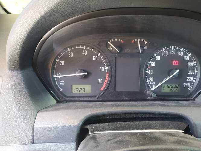
Monitor your Mercedes’ performance in real-time, tracking parameters such as engine RPM, vehicle speed, and coolant temperature. This can help you identify potential issues before they become serious problems.
8.2. Fuel Efficiency Analysis
Analyze your fuel efficiency by logging data such as fuel consumption, speed, and RPM. This can help you optimize your driving habits and save money on fuel.
8.3. Diagnostics and Troubleshooting
Use the system to diagnose and troubleshoot issues with your Mercedes. By reading diagnostic trouble codes (DTCs) and monitoring sensor data, you can identify the root cause of problems and avoid costly repairs.
8.4. Fleet Management
For businesses managing a fleet of Mercedes vehicles, an Arduino OBD2 Sparkfun system can provide valuable insights into vehicle usage, maintenance needs, and driver behavior. This can help reduce costs and improve efficiency.
Here are some fleet management applications:
- Tracking Vehicle Usage: Monitor mileage, idle time, and operating hours.
- Predictive Maintenance: Identify potential maintenance issues before they lead to breakdowns.
- Driver Behavior Monitoring: Track speeding, hard braking, and other unsafe driving behaviors.
By centralizing this data, fleet managers can make informed decisions and optimize their operations.
8.5. Enhancing Vehicle Security
An Arduino OBD2 Sparkfun system can be used to enhance vehicle security. By monitoring the OBD-II port for unauthorized access and implementing custom alerts, you can protect your Mercedes from theft and tampering.
Here’s how you can implement security measures:
- Unauthorized Access Detection: Monitor the OBD-II port for unusual activity.
- Remote Immobilization: Implement a system to remotely disable the vehicle in case of theft.
- Geofencing: Set up virtual boundaries and receive alerts if the vehicle enters or exits these areas.
By integrating these security features, you can add an extra layer of protection to your Mercedes.
9. The Future of Arduino OBD2 in Automotive Diagnostics
9.1. Integration with AI and Machine Learning
The future of Arduino OBD2 lies in its integration with AI and machine learning technologies. By analyzing the vast amounts of data collected from the OBD2 port, AI algorithms can identify patterns and predict potential issues with greater accuracy.
9.2. Wireless Connectivity and Cloud Integration
Wireless connectivity, such as Bluetooth and Wi-Fi, will allow for seamless integration with cloud-based platforms. This will enable remote monitoring, data analysis, and over-the-air updates.
9.3. Enhanced Customization and Personalization
Future systems will offer even greater customization and personalization, allowing users to tailor the system to their specific needs and preferences. This includes custom displays, alerts, and data analysis tools.
9.4. Predictive Maintenance
Predictive maintenance involves using data analysis to anticipate maintenance needs before failures occur. By continuously monitoring OBD-II data, you can predict when components are likely to fail and schedule maintenance proactively.
Here are some benefits of predictive maintenance:
- Reduced Downtime: Minimize vehicle downtime by addressing issues before they lead to breakdowns.
- Lower Maintenance Costs: Avoid costly emergency repairs by scheduling maintenance proactively.
- Improved Vehicle Reliability: Enhance the reliability of your Mercedes by keeping it in optimal condition.
Predictive maintenance can significantly extend the lifespan of your vehicle and reduce overall operating costs.
9.5. Autonomous Driving Support
As autonomous driving technology advances, Arduino OBD2 systems can play a crucial role in providing real-time data and diagnostics to support autonomous driving functions. This includes monitoring sensor data, detecting anomalies, and providing backup systems in case of failures.
Here’s how Arduino OBD2 can support autonomous driving:
- Sensor Data Validation: Ensure the accuracy and reliability of sensor data used by autonomous driving systems.
- Fault Detection: Identify and report any faults or anomalies in the vehicle’s systems.
- Redundancy: Provide backup systems in case of primary system failures.
By integrating Arduino OBD2 systems, autonomous vehicles can achieve higher levels of safety and reliability.
10. Frequently Asked Questions (FAQ)
Q1: What is the best Arduino board for OBD2 diagnostics?
The Arduino Uno and Nano are popular choices due to their simplicity and wide availability.
Q2: What OBD2 PIDs are supported by my Mercedes?
Consult the OBD2 documentation for your specific Mercedes model to find the supported PIDs.
Q3: How do I parse the OBD2 responses?
The parsing logic depends on the format of the response. Consult the OBD2 documentation for your vehicle to understand the format.
Q4: Can I log the data to an SD card?
Yes, you can log the data to an SD card using an SD card module and the SD library.
Q5: Can I create custom gauges and displays?
Yes, you can create custom gauges and displays using various display technologies, such as OLED screens or TFT displays.
Q6: How do I troubleshoot communication errors?
Check the wiring, baud rate, and initialization commands. Add delays between sending commands and reading responses.
Q7: Is it safe to work with the OBD2 port?
Follow safety precautions, such as disconnecting the vehicle’s battery and avoiding short circuits.
Q8: Can I use this system while driving?
Do not operate the vehicle while programming or troubleshooting the system. Ensure that the system does not interfere with the vehicle’s safety systems.
Q9: How can MERCEDES-DIAGNOSTIC-TOOL.EDU.VN help me?
We offer expert guidance, comprehensive resources, and community support to help you build and troubleshoot your Arduino OBD2 Sparkfun system.
Q10: What are the future trends in Arduino OBD2 diagnostics?
The future lies in integration with AI and machine learning, wireless connectivity, and enhanced customization.
Ready to elevate your Mercedes diagnostics? Contact MERCEDES-DIAGNOSTIC-TOOL.EDU.VN today for expert guidance on Arduino OBD2 Sparkfun setups. Our team is here to help you unlock your vehicle’s full potential. Reach out now via Whatsapp at +1 (641) 206-8880 or visit our website at MERCEDES-DIAGNOSTIC-TOOL.EDU.VN for personalized assistance. Located at 789 Oak Avenue, Miami, FL 33101, United States, we’re dedicated to providing top-tier diagnostic solutions.
 Mercedes-Benz Engine Diagnostics
Unlock deeper insights into your Mercedes’ performance and ensure it runs at its best!