OBD2 became standard in the USA for cars and light trucks in 1996, revolutionizing vehicle diagnostics; explore its history, future and how it can empower Mercedes-Benz owners with MERCEDES-DIAGNOSTIC-TOOL.EDU.VN. This comprehensive guide helps you understand OBD2 implementation timeline, OBD2 protocols, and vehicle diagnostic tools to keep your Mercedes-Benz running smoothly. Discover how this standard has evolved and what it means for modern vehicle maintenance and customization.
Contents
- 1. What is OBD2?
- 2. Is My Car OBD2 Compliant?
- 3. When Did OBD2 Become Standard?
- 4. What is the Future of OBD2?
- 4.1 Electric Vehicles and OBD2
- 4.2 Emerging OBD Standards: WWH-OBD and OBDonUDS
- 4.3 OBD3: Integrating Telematics
- 4.4 Restrictions on Third-Party Data Access
- 5. What are OBD2 Standards?
- 6. Understanding the OBD2 Connector [SAE J1962]
- 6.1 OBD2 Connector Types: A vs. B
- 7. OBD2 and CAN Bus [ISO 15765-4]
- 7.1 OBD2 CAN Identifiers (11-bit, 29-bit)
- 7.2 OBD2 vs. Proprietary CAN Protocols
- 7.3 Bit-Rate and ID Validation
- 7.4 Five Lower-Layer OBD2 Protocols
- 8. How OBD2 Messages are Transported via ISO-TP [ISO 15765-2]
- 9. The OBD2 Diagnostic Message [SAE J1979, ISO 15031-5]
- 9.1 Example: OBD2 Request/Response
- 9.2 The 10 OBD2 Services (aka Modes)
- 9.3 OBD2 Parameter IDs (PID)
- 9.4 OBD2 PID Overview Tool
- 10. How to Log and Decode OBD2 Data
- 10.1 Test Bit-Rate, IDs, and Supported PIDs
- 10.2 Configure OBD2 PID Requests
- 10.3 DBC Decode Raw OBD2 Data
- 11. OBD2 Multi-Frame Examples [ISO-TP]
- 11.1 Example 1: OBD2 Vehicle Identification Number (VIN)
- 11.2 Example 2: OBD2 Multi-PID Request (6x)
- 11.3 Example 3: OBD2 Diagnostic Trouble Codes (DTCs)
- 12. OBD2 Data Logging – Use Case Examples
- 12.1 Logging Data from Cars
- 12.2 Real-Time Car Diagnostics
- 12.3 Predictive Maintenance
- 12.4 Vehicle Blackbox Logger
- 13. Understanding OBD2 for Your Mercedes-Benz
- 14. How MERCEDES-DIAGNOSTIC-TOOL.EDU.VN Can Help
- 15. Call to Action
1. What is OBD2?
OBD2 (On-Board Diagnostics II) represents your vehicle’s integrated self-diagnostic system. It is a standardized protocol that facilitates the extraction of diagnostic trouble codes (DTCs) and real-time data through the OBD2 connector. This standardized system allows vehicle owners and technicians to access vital information about the vehicle’s health and performance.
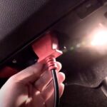
Have you ever noticed the malfunction indicator light on your dashboard? This light, commonly referred to as the “check engine light,” is your vehicle signaling a potential issue. Mechanics utilize an OBD2 scanner to pinpoint the problem by connecting it to the OBD2 16-pin connector, usually located near the steering wheel. The scanner transmits ‘OBD2 requests’ to the vehicle, and the vehicle responds with ‘OBD2 responses’, which may include data such as speed, fuel level, or DTCs. This process significantly expedites the troubleshooting of vehicle issues.
2. Is My Car OBD2 Compliant?
In most cases, the answer is yes. The vast majority of modern, non-electric vehicles are equipped with OBD2 systems, often operating on the CAN bus. However, for older vehicles, the presence of a 16-pin OBD2 connector does not automatically guarantee OBD2 compatibility. To ascertain compliance, consider the vehicle’s origin and the year it was purchased new:
-
United States: Mandatory for cars and light trucks manufactured from 1996 onwards.
-
European Union: Required for gasoline cars from 2001 and diesel cars from 2003 (EOBD).
-
Medium-Duty Vehicles: Required in the US from 2005.
-
Heavy-Duty Vehicles: Required in the US from 2010.
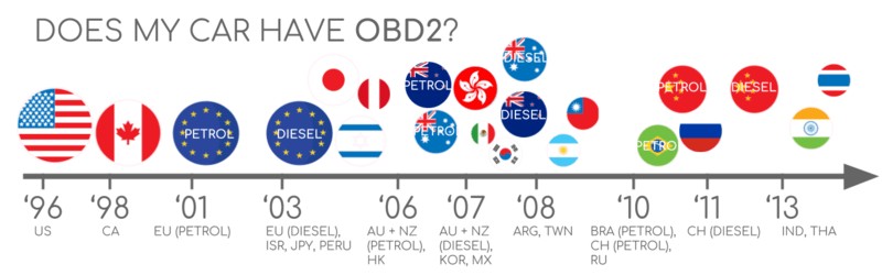 Does My Car Have OBD2?
3. When Did OBD2 Become Standard?
OBD2’s genesis can be traced back to California, where the California Air Resources Board (CARB) mandated OBD in all new vehicles from 1991 onwards for the purpose of emission control. The Society of Automotive Engineers (SAE) played a pivotal role by recommending the OBD2 standard, which standardized DTCs and the OBD connector across different manufacturers (SAE J1962).
The implementation of the OBD2 standard occurred gradually:
- 1996: OBD2 became compulsory in the USA for cars and light trucks.
- 2001: Required in the EU for gasoline cars.
- 2003: Required in the EU for diesel cars (EOBD).
- 2005: OBD2 was required in the US for medium-duty vehicles.
- 2008: US cars were required to use ISO 15765-4 (CAN) as the foundation for OBD2.
- 2010: OBD2 was finally mandated in US heavy-duty vehicles.
4. What is the Future of OBD2?
OBD2 is expected to remain relevant, but its form and function are likely to evolve. Here are some significant trends:
4.1 Electric Vehicles and OBD2
Originally, legislated OBD2 was designed for emission control. Consequently, electric vehicles (EVs) are not typically required to support OBD2 in any manner. Many modern EVs do not support standard OBD2 requests, instead utilizing OEM-specific UDS communication. This often makes it impossible to decode data from these EVs unless the decoding rules have been reverse engineered.
4.2 Emerging OBD Standards: WWH-OBD and OBDonUDS
Given the limitations of current OBD2 implementations, modern alternatives have emerged, including WWH-OBD (World Wide Harmonized OBD) and OBDonUDS (OBD on UDS). These protocols aim to streamline and enhance OBD communication by using the UDS protocol as a foundation.
4.3 OBD3: Integrating Telematics
In the era of connected cars, manual emission control checks can be cumbersome and expensive. OBD3 proposes adding telematics to all vehicles. This involves incorporating a small radio transponder, similar to those used in bridge tolls, into all cars. This transponder would transmit the vehicle identification number (VIN) and DTCs via WiFi to a central server for verification.
Many devices already facilitate the transfer of CAN or OBD2 data via WiFi/cellular, such as the CANedge2 WiFi CAN logger and the CANedge3 3G/4G CAN logger. While this approach offers cost savings and convenience, it raises political concerns related to surveillance.
4.4 Restrictions on Third-Party Data Access
The OBD2 protocol was initially designed for stationary emission controls. However, it is now widely used by third parties to generate real-time data through OBD2 dongles and CAN loggers. Some manufacturers are seeking to restrict this access:
“OBD has been designed to service cars in repair shops. In no way has it been intended to allow third parties to build a form of data-driven economy on the access through this interface.” – Christoph Grote, SVP Electronics, BMW (2017)
The proposal involves disabling OBD2 functionality during driving and instead collecting data on a central server. This would give manufacturers control over automotive big data and reduce the risk of car hacking. However, many perceive this as a commercial move that could disrupt the market for third-party OBD2 services.
5. What are OBD2 Standards?
On-board diagnostics, or OBD2, is a higher-layer protocol, akin to a language. CAN serves as a communication method, similar to a phone. This positions OBD2 alongside other CAN-based higher-layer protocols such as J1939, CANopen, and NMEA 2000. OBD2 standards define the OBD2 connector, lower-layer protocols, OBD2 parameter IDs (PID), and more.
The standards can be represented using a 7-layer OSI model. Several layers are covered by both SAE and ISO standards, reflecting standards for OBD defined in the USA (SAE) and the EU (ISO). Many of these standards are technically equivalent; for example, SAE J1979 is comparable to ISO 15031-5, and SAE J1962 is similar to ISO 15031-3.
6. Understanding the OBD2 Connector [SAE J1962]
The 16-pin OBD2 connector enables easy access to your car’s data and is defined in the SAE J1962 / ISO 15031-3 standard. The illustration depicts a Type A OBD2 pin connector, also known as the Data Link Connector (DLC).
Key points to note:
- The connector is typically located near the steering wheel but may be hidden.
- Pin 16 provides battery power, often when the ignition is off.
- The OBD2 pinout varies depending on the communication protocol.
- The most common lower-layer protocol is CAN bus, meaning that pins 6 (CAN-H) and 14 (CAN-L) are usually connected.
6.1 OBD2 Connector Types: A vs. B
In practice, both Type A and Type B OBD2 connectors may be encountered. Type A is commonly found in cars, while Type B is typical in medium and heavy-duty vehicles. The two types share similar OBD2 pinouts but provide different power supply outputs (12V for Type A and 24V for Type B). The baud rate often differs as well, with cars typically using 500K and heavy-duty vehicles using 250K (though 500K is becoming more common).
To differentiate between the two types, note that the Type B OBD2 connector has an interrupted groove in the middle. A Type B OBD2 adapter cable is compatible with both types A and B, while a Type A cable will not fit into a Type B socket.
7. OBD2 and CAN Bus [ISO 15765-4]
Since 2008, CAN bus has been the mandatory lower-layer protocol for OBD2 in all cars sold in the US, as per ISO 15765. ISO 15765-4 (also known as Diagnostics over CAN or DoCAN) specifies restrictions applied to the CAN standard (ISO 11898). It standardizes the CAN interface for test equipment, focusing on the physical, data link, and network layers:
- The CAN bus bit-rate must be either 250K or 500K.
- The CAN IDs can be 11-bit or 29-bit.
- Specific CAN IDs are used for OBD requests/responses.
- The diagnostic CAN frame data length must be 8 bytes.
- The OBD2 adapter cable must be a maximum of 5 meters.
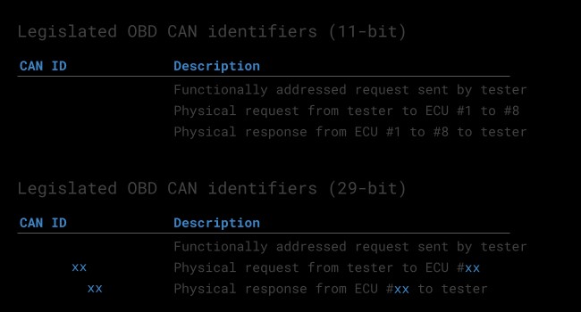
7.1 OBD2 CAN Identifiers (11-bit, 29-bit)
All OBD2 communication involves request/response messages. In most cars, 11-bit CAN IDs are used for OBD2 communication. The ‘Functional Addressing’ ID is 0x7DF, which corresponds to asking all OBD2-compatible ECUs if they have data to report on the requested parameter. CAN IDs 0x7E0-0x7E7 can be used to perform ‘Physical Addressing’ requests from specific ECUs (less commonly used).
ECUs can respond with 11-bit IDs 0x7E8-0x7EF. The most common response ID is 0x7E8 (ECM, Engine Control Module), and to some extent 0x7E9 (TCM, Transmission Control Module). In some vehicles, OBD2 communication uses extended 29-bit CAN identifiers instead of 11-bit CAN identifiers. The ‘Functional Addressing’ CAN ID is 0x18DB33F1. If the vehicle responds, responses with CAN IDs 0x18DAF100 to 0x18DAF1FF (typically 18DAF110 and 18DAF11E) will be seen. The response ID is also sometimes shown in the ‘J1939 PGN’ form, specifically the PGN 0xDA00 (55808), which in the J1939-71 standard is marked as ‘Reserved for ISO 15765-2’.
 OBD2 OBD CAN bus Identifiers 7DF 7E8 7E0
7.2 OBD2 vs. Proprietary CAN Protocols
Your car’s electronic control units (ECUs) do not rely on OBD2 to function. Each original equipment manufacturer (OEM) implements its own proprietary CAN protocols, which may be specific to the vehicle brand, model, and year. If you are not the OEM, you will typically not be able to interpret this data unless you can reverse engineer it.
If you connect a CAN bus data logger to your car’s OBD2 connector, you may see the OEM-specific CAN data, typically broadcast at a rate of 1000-2000 frames/second. However, in many newer cars, a ‘gateway’ blocks access to this CAN data and only enables OBD2 communication via the OBD2 connector.
Think of OBD2 as an ‘extra’ higher-layer protocol in parallel to the OEM-specific protocol.
7.3 Bit-Rate and ID Validation
OBD2 may use one of two bit-rates (250K, 500K) and one of two CAN ID lengths (11-bit, 29-bit), resulting in four potential combinations. Modern cars commonly use 500K and 11-bit IDs, but external tools should systematically verify this. ISO 15765-4 provides recommendations for performing a systematic initialization sequence to determine the relevant combination, leveraging that OBD2-compliant vehicles must respond to a specific mandatory OBD2 request and that transmitting data with an incorrect bit-rate will cause CAN error frames.
Newer versions of ISO 15765-4 consider that vehicles may support OBD communication via OBDonUDS rather than OBDonEDS. Most of this article focuses on OBD2/OBDonEDS (OBD on emission diagnostic service as per ISO 15031-5/SAE J1979) as opposed to WWH-OBD/OBDonUDS (OBD on Unified Diagnostic Service as per ISO 14229, ISO 27145-3/SAE J1979-2).
To test for the ‘protocol’ of OBDonEDS vs OBDonUDS, a test tool may add additional request messages, specifically sending UDS requests with 11-bit/29-bit functional address IDs for service 0x22 and data identifier (DID) 0xF810 (protocol identification). Vehicles that support OBDonUDS must have ECUs that reply to this DID. OBDonEDS (aka OBD2, SAE OBD, EOBD, or ISO OBD) is used in most non-EV cars today, while WWH-OBD is primarily used in EU trucks/buses.
7.4 Five Lower-Layer OBD2 Protocols
CAN serves as the lower-layer basis for OBD2 in most cars per ISO 15765. Inspecting an older car (pre-2008), it is useful to know the other four lower-layer protocols used as the basis for OBD2, along with their pinouts:
- ISO 15765 (CAN bus): Mandatory in US cars since 2008 and widely used today.
- ISO14230-4 (KWP2000): Common protocol for 2003+ cars in Asia.
- ISO 9141-2: Used in EU, Chrysler & Asian cars in 2000-04.
- SAE J1850 (VPW): Used mostly in older GM cars.
- SAE J1850 (PWM): Used mostly in older Ford cars.
8. How OBD2 Messages are Transported via ISO-TP [ISO 15765-2]
All OBD2 data is communicated on the CAN bus through a transport protocol called ISO-TP (ISO 15765-2). This enables communication of payloads that exceed 8 bytes, which is necessary when extracting the Vehicle Identification Number (VIN) or Diagnostic Trouble Codes (DTCs). ISO 15765-2 facilitates segmentation, flow control, and reassembly.
However, OBD2 data often fits in a single CAN frame. ISO 15765-2 specifies the use of a ‘Single Frame’ (SF), implying that the 1st data byte (the PCI field) contains the payload length (excluding padding), leaving 7 bytes for OBD2-related communication.
9. The OBD2 Diagnostic Message [SAE J1979, ISO 15031-5]
To better understand OBD2 on CAN, consider a raw ‘Single Frame’ OBD2 CAN message. In simplified terms, an OBD2 message includes an identifier, data length (PCI field), and data. The data is split into Mode, parameter ID (PID), and data bytes.
9.1 Example: OBD2 Request/Response
Consider this example request/response for the parameter ‘Vehicle Speed’. An external tool sends a request message to the car with CAN ID 0x7DF and 2 payload bytes: Mode 0x01 and PID 0x0D. The car responds via CAN ID 0x7E8 and 3 payload bytes, including the value of Vehicle Speed in the 4th byte, 0x32 (50 in decimal form). By looking up the decoding rules for OBD2 PID 0x0D, we determine that the physical value is 50 km/h.
9.2 The 10 OBD2 Services (aka Modes)
There are 10 OBD2 diagnostic services (or modes). Mode 0x01 shows current real-time data, while others are used to show/clear diagnostic trouble codes (DTCs) or show freeze frame data. Vehicles do not have to support all OBD2 modes and may support modes outside the 10 standardized modes (OEM-specific OBD2 modes). In OBD2 messages, the mode is in the 2nd byte. In the request, the mode is included directly (e.g., 0x01), while in the response, 0x40 is added to the mode (resulting in 0x41).
9.3 OBD2 Parameter IDs (PID)
Each OBD2 mode contains parameter IDs (PIDs). For example, mode 0x01 contains ~200 standardized PIDs with real-time data on speed, RPM, and fuel level. However, a vehicle does not have to support all OBD2 PIDs in a mode; most vehicles only support a small subset. If an emissions-related ECU supports any OBD2 services, it must support mode 0x01 PID 0x00. In response to this PID, the vehicle ECU informs whether it supports PIDs 0x01-0x20, making PID 0x00 useful as a fundamental ‘OBD2 compatibility test’. Further, PIDs 0x20, 0x40, …, 0xC0 can be used to determine the support for the remaining mode 0x01 PIDs.
9.4 OBD2 PID Overview Tool
In the appendices of SAE J1979 and ISO 15031-5, you can find scaling info for standard OBD2 PIDs, which allows you to decode the data into physical values. If you need to look up a mode 0x01 PID, check out our OBD2 PID overview tool. This helps you construct OBD2 request frames and dynamically decode the OBD2 responses.
OBD2 PID overview tool
10. How to Log and Decode OBD2 Data
This section provides a practical example of how to log OBD2 data with the CANedge CAN bus data logger. The CANedge allows configuring custom CAN frames to be transmitted, which allows it to be used for OBD2 logging. Once configured, the device can be easily connected to your vehicle via our OBD2-DB9 adapter cable.
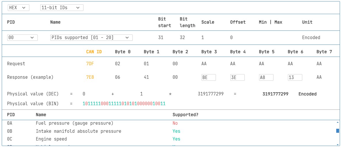
10.1 Test Bit-Rate, IDs, and Supported PIDs
ISO 15765-4 describes how to determine which bit-rate and IDs are used by a specific vehicle. You can test this with the CANedge as below:
- Send CAN frame at 500K and check if successful (else try 250K).
- Use the identified bit-rate for subsequent communication.
- Send multiple ‘Supported PIDs’ requests and review the results.
- Based on response IDs, you can determine 11-bit vs. 29-bit.
- Based on response data, you can see what PIDs are supported.
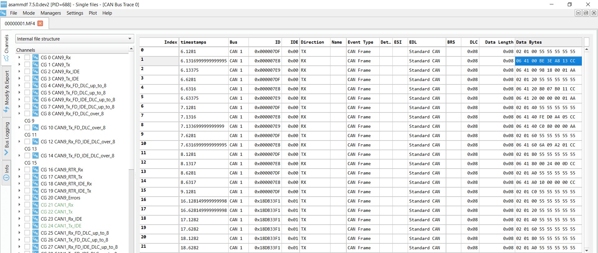
We provide plug & play configs to perform the above tests. Most 2008+ non-EV cars support 40-80 PIDs via a 500K bit-rate, 11-bit CAN IDs, and the OBD2/OBDonEDS protocol. As exemplified in the asammdf GUI screenshot, it is common to see multiple responses to a single OBD request. This is because we use the 0x7DF request ID, which polls all ECUs for a response. Since all OBD2/OBDonEDS-compliant ECUs must support service 0x01 PID 0x00, there are often many responses to this PID. For subsequent ‘Supported PIDs’ requests, fewer ECUs respond.
Note that the ECM ECU (0x7E8) itself supports all the PIDs that are supported by other ECUs in this example, meaning the busload may be reduced by only asking specifically this ECU for responses by changing to the ‘Physical Addressing’ CAN ID 0x7E0 for subsequent communication.
 OBD2 bit rate test
 OBD2 Supported PIDs Test
 Review supported PIDs via OBD2 lookup tool
10.2 Configure OBD2 PID Requests
You now know which OBD2 PIDs are supported by your vehicle and what bit-rate and CAN IDs to use when requesting them. Next, configure your transmit list with PIDs of interest.
Consider:
- CAN IDs: Shift to ‘Physical Addressing’ request IDs (e.g., 0x7E0) to avoid multiple responses to each request.
- Spacing: Add 300-500 ms between each OBD2 request (spamming the ECUs may cause them to not respond).
- Battery drain: Use triggers to stop transmitting when the vehicle is inactive (to avoid ‘waking up’ ECUs).
- Filters: Add filters to only record OBD2 responses (e.g., if your vehicle also outputs OEM-specific CAN data).
Once configured, the device is ready to log raw OBD2 data!
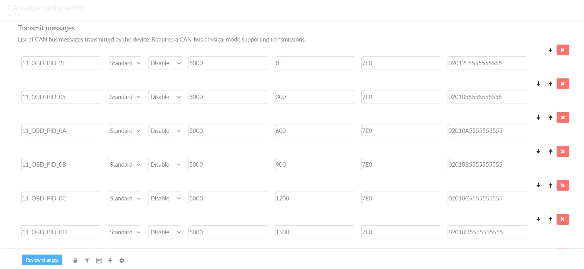 obd2-transmit-list-example-canedge
10.3 DBC Decode Raw OBD2 Data
To analyze/visualize your data, you need to decode the raw OBD2 data into ‘physical values’ (like km/h or degC). The necessary decoding information can be found in ISO 15031-5/SAE J1979. For convenience, we provide a free OBD2 DBC file that makes it easy to DBC decode raw OBD2 data in most CAN bus software tools. Decoding OBD2 data is a bit more complex than regular CAN signals because different OBD2 PIDs are transported using the same CAN ID (e.g., 0x7E8). As such, the CAN ID is not sufficient to uniquely identify what signals are encoded in the payload.
One must leverage both the CAN ID, OBD2 mode, and OBD2 PID to identify the signal. This is a form of multiplexing referred to as ‘extended multiplexing’, which can be implemented in DBC files.
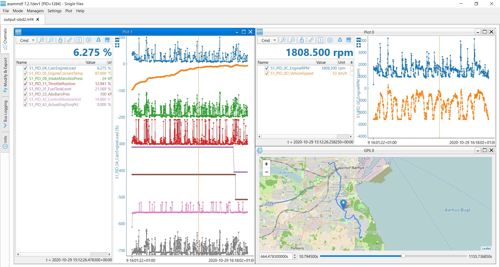 OBD2 data decoded visual plot asammdf CAN bus DBC file
11. OBD2 Multi-Frame Examples [ISO-TP]
All OBD2 data is communicated using the ISO-TP (transport protocol) as per ISO 15765-2. Most examples so far reflect single-frame communication. This section provides examples of multi-frame communication. Multi-frame OBD2 communication requires flow control frames. In practice, this can be done by transmitting a static flow control frame, e.g., 50 ms after the initial request frame, as per the CANedge configuration example shown. Further, multi-frame OBD2 responses require CAN software/API tools that support ISO-TP, like the CANedge MF4 decoders.
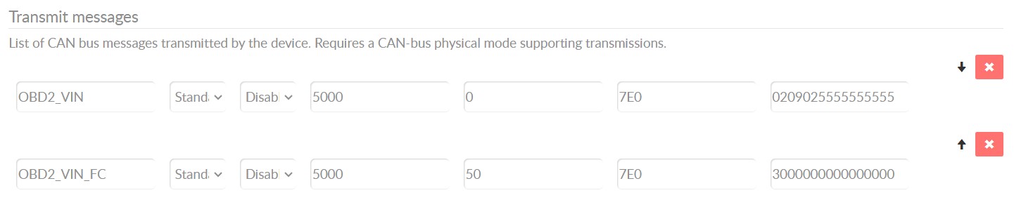 OBD2-multi-frame-request-message-vehicle-identification-number
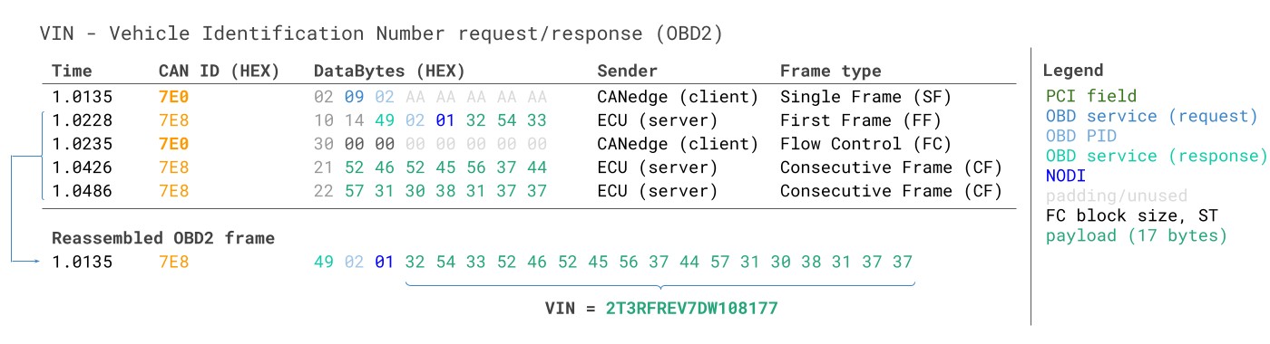
11.1 Example 1: OBD2 Vehicle Identification Number (VIN)
The Vehicle Identification Number (VIN) is relevant to telematics, diagnostics, and more. To extract the VIN from a vehicle using OBD2 requests, use mode 0x09 and PID 0x02:
 VIN Vehicle Identification Number OBD2 Example multi-frame
The tester tool sends a Single Frame request with the PCI field (0x02), request service identifier (0x09), and PID (0x02). The vehicle responds with a First Frame containing the PCI, length (0x014 = 20 bytes), mode (0x49, i.e., 0x09 + 0x40), and PID (0x02). Following the PID is the byte 0x01, which is the Number Of Data Items (NODI), in this case 1. The remaining 17 bytes equal the VIN and can be translated from HEX to ASC.
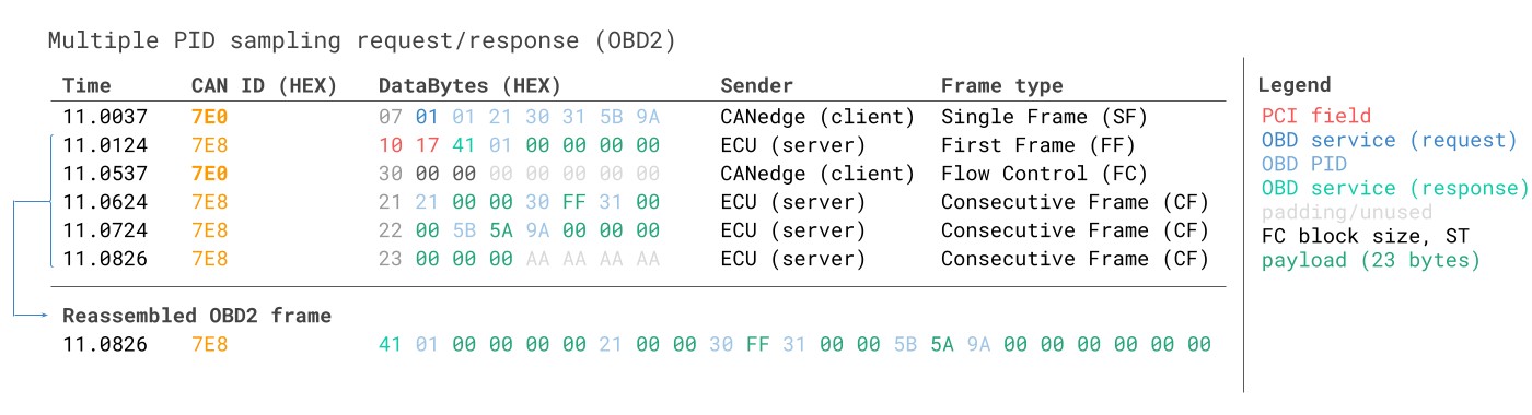
11.2 Example 2: OBD2 Multi-PID Request (6x)
External tools can request up to 6 mode 0x01 OBD2 PIDs in a single request frame. The ECU shall respond with data for supported PIDs (with unsupported PIDs left out of the response), if necessary across multiple frames as per ISO-TP. This is a powerful feature that lets you collect OBD2 data at higher frequency and efficiency, though it also implies that the signal encoding is specific to your request method, making e.g., the use of generic OBD2 DBC files difficult for such use cases. We do not recommend using this method in practice. Below, we provide an example trace of what this may look like:
 Requesting multiple PIDs in one request
The multi-frame response is similar to the VIN example, though with the twist that the payload includes the requested PIDs as well as the data for each of them. The PIDs in the example are ordered similarly to how they are requested, which is common in practice (but not strictly required by the ISO 15031-5 standard). Decoding this response via e.g., DBC files is very difficult in practice, and hence we would not recommend using this approach for practical data logging unless you are working with a tool that has built-in support specifically for this.
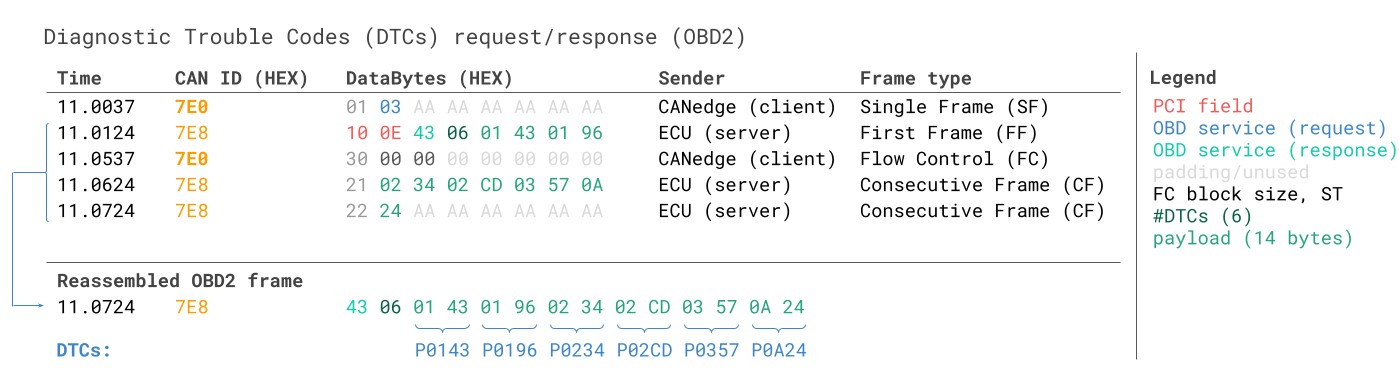
11.3 Example 3: OBD2 Diagnostic Trouble Codes (DTCs)
You can use OBD2 to request emissions-related Diagnostic Trouble Codes (DTCs) using mode 0x03, i.e., ‘Show stored Diagnostic Trouble Codes’. No PID is included in the request. The targeted ECU(s) will then respond with the number of DTCs they have stored (including potentially 0 if they have none), with each DTC taking up 2 data bytes. As a result, multi-frame responses are necessary when more than 2 DTCs are stored.
The 2-byte DTC value is typically split into two parts, as per ISO 15031-5/ISO 15031-6. The first 2 bits define the ‘category’, while the remaining 14 bits define a 4-digit code (displayed in hexadecimal). The decoded DTC values can be looked up in various OBD2 DTC lookup tools like repairpal.com.
Below is an example showing a request to an ECU with 6 DTCs stored.
 OBD2 Diagnostic Trouble Codes DTC CAN Bus Request Response Example
12. OBD2 Data Logging – Use Case Examples
OBD2 data from cars and light trucks can be used in various use cases:
12.1 Logging Data from Cars
OBD2 data from cars can be used to reduce fuel costs, improve driving, test prototype parts, and for insurance purposes.
12.2 Real-Time Car Diagnostics
OBD2 interfaces can be used to stream human-readable OBD2 data in real-time, e.g., for diagnosing vehicle issues.
12.3 Predictive Maintenance
Cars and light trucks can be monitored via IoT OBD2 loggers in the cloud to predict and avoid breakdowns.
12.4 Vehicle Blackbox Logger
An OBD2 logger can serve as a ‘blackbox’ for vehicles or equipment, providing data for disputes or diagnostics.
13. Understanding OBD2 for Your Mercedes-Benz
For Mercedes-Benz owners, understanding OBD2 provides valuable insights into your vehicle’s health and performance. By utilizing OBD2 tools, you can:
- Read Diagnostic Trouble Codes (DTCs): Identify the cause of the check engine light and potential issues.
- Monitor Real-Time Data: Track parameters such as engine temperature, RPM, and speed.
- Perform Routine Maintenance: Ensure your Mercedes-Benz is running optimally.
- Unlock Hidden Features: Customize your driving experience by accessing advanced settings.
14. How MERCEDES-DIAGNOSTIC-TOOL.EDU.VN Can Help
Navigating the complexities of OBD2 and applying it to your Mercedes-Benz can seem daunting. That’s where MERCEDES-DIAGNOSTIC-TOOL.EDU.VN comes in. We provide:
- Expert Guidance: Step-by-step instructions on using OBD2 tools with your Mercedes-Benz.
- Comprehensive Diagnostics: Detailed explanations of DTCs and what they mean for your vehicle.
- Customization Options: Insights into unlocking hidden features and personalizing your driving experience.
- Maintenance Tips: Proactive advice on keeping your Mercedes-Benz in top condition.
With MERCEDES-DIAGNOSTIC-TOOL.EDU.VN, you gain the knowledge and tools to confidently manage your Mercedes-Benz’s diagnostics and maintenance.
15. Call to Action
Ready to take control of your Mercedes-Benz’s diagnostics and maintenance? Contact MERCEDES-DIAGNOSTIC-TOOL.EDU.VN today for expert guidance on OBD2 tools, unlocking hidden features, and personalized support.
- Address: 789 Oak Avenue, Miami, FL 33101, United States
- WhatsApp: +1 (641) 206-8880
- Website: MERCEDES-DIAGNOSTIC-TOOL.EDU.VN
Let us help you keep your Mercedes-Benz