The increasing number of ECUs significantly impacts DTC diagnosis complexity, demanding advanced tools and expertise, but MERCEDES-DIAGNOSTIC-TOOL.EDU.VN offers innovative solutions. Our comprehensive diagnostic tools and services provide clear, step-by-step guidance for Mercedes-Benz owners and technicians. Unlock hidden features, simplify repairs, and maintain your vehicle effortlessly with our expertise in automotive diagnostics, ECU programming, and vehicle maintenance.
Contents
- 1. Understanding the Evolution of DTCs
- 1.1. From Flashing Codes to Standardized DTCs
- 1.2. The Role of OBD and UDS Standards
- 1.3. Proprietary Diagnostic Procedures
- 2. The Significance of Exchange Formats for DTCs
- 2.1. DEXT Format in AUTOSAR
- 2.2. ODX Format in ASAM
- 2.3. Benefits of Using Common Exchange Formats
- 3. How DTCs Work in the Control Unit
- 3.1. Application Software with Diagnostic Functions (Monitor)
- 3.2. Diagnostic Events and the Diagnostic Manager (DM)
- 3.3. OEM’s Role in Determining DTC Usage
- 3.4. Connecting Events to DTCs
- 4. Debouncing of Events: Preventing False Positives
- 4.1. Time-Based Debouncing
- 4.2. Counter-Based Debouncing
- 4.3. Internal Debouncing
- 4.4. Additional Settings Influencing DTC Behavior
- 5. Function Deactivation and the Function Inhibition Manager (FIM)
- 5.1. FMEA and Vehicle Reactions
- 5.2. Implementing FMEA in the Control Unit
- 6. The Operation Cycle and DTC Dynamics
- 6.1. Defining the Operation Cycle
- 6.2. DTC Status and ISO 14229-1:2013 (UDS Standard)
- 6.3. Dynamic Behavior of DTCs
- 7. The Error Memory (Event-Memory): Recording Environmental Conditions
- 7.1. DTC Snapshot Data (FreezeFrames)
- 7.2. Data Structure of Snapshot Records
- 8. Extended Data: Capturing Additional Diagnostic Information
- 8.1. Contents of the Extended Data Block
- 8.2. Record Numbers and Data Structure
- 8.3. Number of Stored ExtendedDataRecords
- 9. The Diagnostic Communication Manager (DCM): Transmitting Data to the Tester
- 9.1. Encoding and Transmitting DTCs
- 9.2. The DTC in the Diagnose Tester (ODX)
- 9.3. Additional Challenges for Testers
- 10. Achieving a Single Source of Truth for Diagnostic Data
- 10.1. Combining Information in a Common Database
- 10.2. Uniform Data Assignment Process
- 10.3. Benefits of a Single Source of Truth
- 11. How MERCEDES-DIAGNOSTIC-TOOL.EDU.VN Can Help
- 11.1. Comprehensive Diagnostic Tools
- 11.2. Step-by-Step Guidance
- 11.3. Unlocking Hidden Features
- 11.4. Expert Support
- 12. FAQ: Diagnostic Trouble Codes (DTCs)
- 12.1. What is a Diagnostic Trouble Code (DTC)?
- 12.2. How are DTCs Generated?
- 12.3. How Can I Read DTCs?
- 12.4. What Do DTCs Mean?
- 12.5. Can I Fix a Problem Based Solely on a DTC?
- 12.6. What is Freeze Frame Data?
- 12.7. How Do I Clear DTCs?
- 12.8. Will Clearing DTCs Affect My Vehicle’s Performance?
- 12.9. What is the Difference Between Generic and Manufacturer-Specific DTCs?
- 12.10. Where Can I Find More Information About DTCs?
- 13. Ready to Simplify Your Mercedes-Benz Diagnostics?
1. Understanding the Evolution of DTCs
Diagnostic Trouble Codes (DTCs) have evolved significantly, moving from simple flashing codes to complex 2-byte (OBD legislated) and 3-byte (UDS standardized) codes. This evolution reflects the increasing complexity of vehicle electronics. Let’s delve deeper into this transformation:
1.1. From Flashing Codes to Standardized DTCs
In the early days of automotive diagnostics, error codes were rudimentary, often communicated through flashing lights on the dashboard. Technicians would count these flashes to identify the problem. However, this system was limited in its ability to represent the intricate issues arising in modern vehicles.
With the advent of sophisticated electronic control units (ECUs), the need for more detailed and standardized diagnostic codes became apparent. This led to the development of 2-byte DTCs, mandated by OBD (On-Board Diagnostics) regulations, and later, 3-byte DTCs, standardized under UDS (Unified Diagnostic Services).
1.2. The Role of OBD and UDS Standards
The OBD standard was initially introduced to monitor emissions-related components and systems. It required vehicles to report standardized DTCs, making it easier for technicians to diagnose and repair emission-related issues. Over time, the scope of OBD expanded to include other vehicle systems.
UDS, on the other hand, is a more comprehensive diagnostic protocol that provides a standardized way to access and diagnose various vehicle systems. It offers a wider range of diagnostic services and supports more complex DTCs, enabling technicians to pinpoint issues with greater precision.
1.3. Proprietary Diagnostic Procedures
Despite the standardization efforts, some vehicle manufacturers still employ proprietary diagnostic procedures. These procedures often involve specialized tools and software, making it challenging for independent repair shops to service certain vehicles.
However, at MERCEDES-DIAGNOSTIC-TOOL.EDU.VN, we strive to provide solutions that bridge this gap. Our diagnostic tools are designed to support both standardized and proprietary diagnostic protocols, empowering technicians to diagnose and repair a wide range of vehicles, including Mercedes-Benz models, with confidence.
2. The Significance of Exchange Formats for DTCs
Efficient troubleshooting and vehicle repair rely heavily on effective data exchange formats. Vehicle manufacturers and suppliers are increasingly collaborating to use common formats, such as DEXT (AUTOSAR) and ODX (ASAM), to reduce costs and streamline processes.
2.1. DEXT Format in AUTOSAR
DEXT (Diagnostic Exchange Format) is a standardized format used within the AUTOSAR (Automotive Open System Architecture) framework for embedded electronics development. It facilitates the exchange of diagnostic information between different software components and ECUs within a vehicle.
By using DEXT, developers can ensure consistency and interoperability across different parts of the vehicle’s electronic system. This simplifies the integration of new components and reduces the risk of diagnostic errors.
2.2. ODX Format in ASAM
ODX (Open Diagnostic data eXchange) is a comparable format developed by ASAM (Association for Standardization of Automation and Measuring Systems) for off-board diagnostics. It provides a standardized way to represent diagnostic data, such as DTCs, parameters, and test routines, in a machine-readable format.
ODX enables diagnostic tools to interpret and process diagnostic data from different vehicle manufacturers consistently. This simplifies the development of diagnostic applications and reduces the need for vehicle-specific diagnostic software.
2.3. Benefits of Using Common Exchange Formats
The use of common exchange formats like DEXT and ODX offers several benefits:
- Cost Reduction: By standardizing diagnostic data, manufacturers can reduce the cost of developing and maintaining diagnostic tools and software.
- Improved Efficiency: Standardized formats streamline the diagnostic process, enabling technicians to diagnose and repair vehicles more quickly and efficiently.
- Enhanced Interoperability: Common formats ensure that diagnostic tools from different vendors can work together seamlessly, providing technicians with greater flexibility and choice.
- Simplified Integration: Standardized data formats simplify the integration of new components and systems into the vehicle’s electronic architecture.
3. How DTCs Work in the Control Unit
The journey of a DTC from its detection in an electronic control unit to its diagnosis in the workshop involves several steps. Understanding this process is crucial for effective troubleshooting.
3.1. Application Software with Diagnostic Functions (Monitor)
Application software within the ECU continuously monitors signals to ensure they remain within predefined limits. These monitors, also known as diagnostic functions, detect deviations from the expected values and signal these events to the Diagnostic Manager (DM).
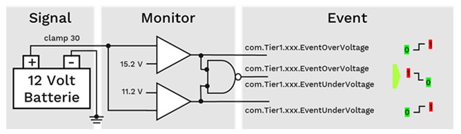 One monitor for battery monitoring with two events
The actual monitoring function, including the specific limit values (e.g., 11.2V and 15.2V for battery voltage), is proprietary to the manufacturer. However, the events triggered by these monitors are typically defined in the DEXT format.
3.2. Diagnostic Events and the Diagnostic Manager (DM)
When a monitor detects a fault, it generates a diagnostic event that is associated with a specific DTC. This event is then transmitted to the DM, which is responsible for managing and storing DTCs.
The DM plays a crucial role in the diagnostic process by:
- Collecting and storing DTCs.
- Managing the status of DTCs (e.g., pending, confirmed, cleared).
- Providing access to DTC information for diagnostic tools.
- Triggering fault reactions based on the severity of the DTCs.
3.3. OEM’s Role in Determining DTC Usage
Original Equipment Manufacturers (OEMs) typically define the DTCs to be used uniformly across their vehicles. This ensures consistency in diagnostic procedures and simplifies the training of technicians.
Several events can be assigned to the same DTC. For example, both “EventOverVoltage” and “EventUnderVoltage” could be assigned to the same DTC, such as “PowerSupply.”
An authoring tool should link the events of the monitors with the DTC of the respective OEM for an ECU. Since not every monitor has to send an event, but every DTC in DM needs at least 4 bytes of memory, unused DTC must be removed.
3.4. Connecting Events to DTCs
The connection between diagnostic events and DTCs is established using authoring tools. These tools allow developers to link specific events from the monitors to the corresponding DTCs defined by the OEM.
It’s important to note that not every monitor needs to send an event, but every DTC in the DM requires a certain amount of memory (e.g., 4 bytes). Therefore, unused DTCs should be removed to optimize memory usage.
4. Debouncing of Events: Preventing False Positives
To prevent minor faults from immediately triggering DTCs and associated fault reactions, debouncing strategies are employed. These strategies ensure that a fault is persistent before a DTC is generated.
4.1. Time-Based Debouncing
With time-based debouncing, a fault must be present for a specified duration before it is considered valid and a DTC is generated. For example, the battery voltage must remain too low for several seconds before a DTC is triggered.
This strategy is effective in filtering out transient faults caused by momentary fluctuations in sensor readings or electrical noise.
4.2. Counter-Based Debouncing
Counter-based debouncing involves incrementing or decrementing a counter based on the presence or absence of a fault. The counter is incremented when a fault is detected and decremented when the fault is cleared.
A DTC is generated when the counter reaches a predefined threshold (e.g., 127 for “Confirmed”) and cleared when the counter falls below another threshold (e.g., -128 for “Passed”). This strategy allows for fine-grained control over the debouncing behavior.
4.3. Internal Debouncing
In internal debouncing, the monitor itself is responsible for debouncing events before sending them to the DM. This approach simplifies the DM’s task and reduces the processing load on the ECU.
However, internal debouncing requires careful design of the monitors to ensure that faults are accurately detected and debounced.
4.4. Additional Settings Influencing DTC Behavior
Besides the three debouncing strategies, numerous other settings in DEXT influence the exact behavior of a DTC. These settings include:
- Saving the debounce counter in non-volatile memory: This ensures that the debounce counter is preserved even when the vehicle is turned off, allowing the debouncing process to continue across multiple ignition cycles.
- Resetting the debounce counter at ClearDTC: This resets the debounce counter when a DTC is cleared, ensuring that the fault must be re-detected before a new DTC is generated.
- Resetting the debounce counter at a new operation cycle: This resets the debounce counter at the start of each operation cycle, ensuring that the debouncing process starts from scratch.
5. Function Deactivation and the Function Inhibition Manager (FIM)
When a DTC is stored as confirmed, the vehicle must react appropriately to the error. The Function Inhibition Manager (FIM) implements these reactions, often based on Failure Mode and Effects Analysis (FMEA).
5.1. FMEA and Vehicle Reactions
During vehicle development, manufacturers analyze potential faults and their effects using FMEA. This analysis helps determine the appropriate reactions to each fault, such as disabling certain functions or activating warning lights.
The FIM then implements these reactions in the control unit, ensuring that the vehicle responds safely and predictably to detected faults.
5.2. Implementing FMEA in the Control Unit
The FIM acts as a central point for managing function deactivation based on DTCs. It receives information about confirmed DTCs and triggers the corresponding reactions, such as:
- Disabling specific functions (e.g., ABS, ESP).
- Activating warning lights on the dashboard.
- Limiting engine power or speed.
- Storing fault-related data for later analysis.
By implementing FMEA in the control unit, manufacturers can ensure that the vehicle responds safely and effectively to a wide range of potential faults.
6. The Operation Cycle and DTC Dynamics
The operation cycle is a defined cycle in the vehicle that serves as a pulse for DTC management. It ensures that DTCs are created and recovered appropriately.
6.1. Defining the Operation Cycle
The operation cycle is a specific sequence of events that represents a typical driving scenario. It might include:
- Ignition on.
- Engine start.
- Idling.
- Acceleration.
- Cruising.
- Deceleration.
- Engine stop.
- Ignition off.
This cycle is used to simulate real-world driving conditions and test the vehicle’s diagnostic capabilities.
6.2. DTC Status and ISO 14229-1:2013 (UDS Standard)
Each DTC has a dynamic status defined in ISO 14229-1:2013 (UDS standard). Bits 0 to 6 of the StatusOfDTC describe where the DTC is currently located in its lifecycle.
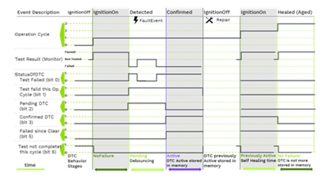 The dynamic behavior of DTC in the vehicle
6.3. Dynamic Behavior of DTCs
The figure above shows an example of the dynamic behavior of a DTC with a cyclic monitor. The cycle is started with “ignition on”.
The dynamic behavior of DTCs is governed by several factors, including:
- The presence or absence of the fault.
- The debouncing strategy employed.
- The operation cycle.
- The clearing of DTCs by a diagnostic tool.
By understanding the dynamic behavior of DTCs, technicians can better diagnose and repair vehicle faults.
7. The Error Memory (Event-Memory): Recording Environmental Conditions
For complex errors, an error code and status are insufficient. The error memory stores environmental conditions like speed, temperature, and velocity to aid in precise error analysis.
7.1. DTC Snapshot Data (FreezeFrames)
Snapshot data, also known as FreezeFrames, captures the values of relevant parameters at the moment a DTC is triggered. This information can be invaluable in diagnosing intermittent faults or faults that are difficult to reproduce.
The retrieval of measured values is already possible without DTC via the ReadDataByIdentifier UDS service. For a meaningful analysis, the measured values must also match the exact time of the triggering event. If a monitor reports “Failed”, the relevant DIDs are temporarily stored with their measured values.
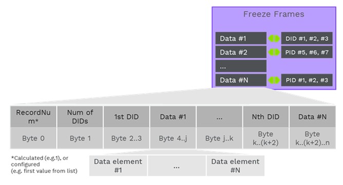 Details of DTC Snapshot Data
7.2. Data Structure of Snapshot Records
The data structure of a snapshot record corresponds to a sequence of individual DIDs from the ReadDataByIdentifier service. There is a large overlap with ODX. If the DID used for a DTC and their data structures are known, the ODX data for readDataByIdentifier and readDTC can be generated from the DEXT information and vice versa.
Snapshot data typically includes parameters such as:
- Engine speed.
- Vehicle speed.
- Engine temperature.
- Airflow.
- Throttle position.
- Fuel pressure.
By analyzing these parameters, technicians can gain valuable insights into the conditions that led to the fault.
8. Extended Data: Capturing Additional Diagnostic Information
The Extended Data Block contains additional information about a DTC, such as cycle counters, aging counters, the time of last occurrences, and dynamic data of algorithms not already in the FreezeFrame data.
8.1. Contents of the Extended Data Block
The Extended Data Block can contain a wide range of information, including:
- Cycle counters: These counters track the number of times a specific event has occurred, such as the number of ignition cycles since the DTC was first detected.
- Aging counters: These counters track the time elapsed since the DTC was last detected.
- Time of last occurrences: This timestamp indicates when the DTC was last triggered.
- Dynamic data of algorithms: This includes data generated by diagnostic algorithms, such as the results of self-tests or the values of internal variables.
8.2. Record Numbers and Data Structure
Similar to DIDs, a 1-byte record number specifies the data structure of the Extended Data block.
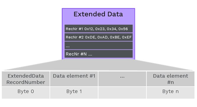 Details of DTC Extended Data
8.3. Number of Stored ExtendedDataRecords
Up to 255 stored ExtendedDataRecords can exist for a DTC. The interpretation of the data is unambiguously determined by its RecordNumber.
The Extended Data Block provides a flexible way to store additional diagnostic information that is not captured by FreezeFrames. This information can be valuable in diagnosing complex or intermittent faults.
9. The Diagnostic Communication Manager (DCM): Transmitting Data to the Tester
The Diagnostic Communication Manager (DCM) is responsible for encoding and transmitting diagnostic data to the tester. It serves as the interface between the ECU and the diagnostic tool.
9.1. Encoding and Transmitting DTCs
With the ReadDTC (0x19) UDS service, a DTC is encoded as a two or three-byte value according to the set DTC format and transmitted via the vehicle bus.
The DCM ensures that the diagnostic data is formatted correctly and transmitted reliably to the diagnostic tool.
9.2. The DTC in the Diagnose Tester (ODX)
Depending on the selected 0x19-ReadDTC subfunction, the FreezeFrame or the corresponding ExtendedData information must be decoded in the tester in addition to the DTC. Of course, the coding of the UDS data in the ECU, based on DEXT, must be identical to the decoding based on ODX.
9.3. Additional Challenges for Testers
There are additional challenges for testers. First of all, he must find out the specific vehicle and select the appropriate VehicleInformationTable (VIT) from ODX. Then the exact SW version of the ECUs installed in the vehicle, or in the case of Adaptive AUTOSAR, the Software Cluster (SWC), is determined by means of variant identification. For this reason, the ODX data of each ECU contains the necessary interpretation for the various software variants.
In addition to data interpretation and variants, other data are also present in ODX, such as audience, speech information and meta-information, which in turn are missing in DEXT.
10. Achieving a Single Source of Truth for Diagnostic Data
ODX and DEXT are exchange formats that have proven themselves in practice and are widely used. A large part of the contents of DEXT and ODX for a DTC are equivalent. However, both formats do not contain all the necessary information for a DTC.
10.1. Combining Information in a Common Database
If all this information is combined in a common database, the only source of truth is created. This ensures that ODX and DEXT files always contain the same information and are therefore consistent. KPIT has already implemented these findings in its K-DCP ECU Editor. The SW developers can focus on the technical characteristics of a DTC and the relevant information and do not need to know any format details. The diagnostic developers then enter additional diagnosis-relevant metadata (texts, variants, …). By jointly storing this data in the KPIT ECU Editor, the necessary ODX and DEXT files are generated consistently, redundancy and contradiction-free at the push of a button and can also be re-imported. Given the complexity of DTCs with their dependencies on extended and freeze-frame data, the diversity that arises due to the variability of the ECU and variants of the software, such a common process with a single common database is almost mandatory. For more information, see the Hanser article “Diagnosis in Adaptive AUTOSAR” from issue 10/2019.
10.2. Uniform Data Assignment Process
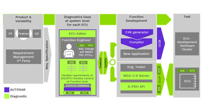 Uniform data assignment process for DTCs and DIDs
10.3. Benefits of a Single Source of Truth
Maintaining a single source of truth for diagnostic data offers several benefits:
- Consistency: Ensures that all diagnostic tools and software use the same data, reducing the risk of errors and misinterpretations.
- Efficiency: Simplifies the development and maintenance of diagnostic tools and software.
- Accuracy: Improves the accuracy of diagnostic information by ensuring that all data is up-to-date and consistent.
- Collaboration: Facilitates collaboration between different teams and organizations involved in vehicle development and diagnostics.
11. How MERCEDES-DIAGNOSTIC-TOOL.EDU.VN Can Help
At MERCEDES-DIAGNOSTIC-TOOL.EDU.VN, we understand the challenges posed by the increasing complexity of DTC diagnosis. That’s why we offer a range of tools and services to help Mercedes-Benz owners and technicians diagnose and repair their vehicles efficiently and effectively.
11.1. Comprehensive Diagnostic Tools
Our diagnostic tools are designed to support a wide range of Mercedes-Benz models and diagnostic protocols. They provide access to DTCs, FreezeFrames, Extended Data, and other diagnostic information, enabling technicians to pinpoint the root cause of vehicle faults quickly.
11.2. Step-by-Step Guidance
We provide clear, step-by-step guidance on how to use our diagnostic tools and interpret the results. Our tutorials and troubleshooting guides are designed to help both experienced technicians and DIY enthusiasts diagnose and repair their Mercedes-Benz vehicles with confidence.
11.3. Unlocking Hidden Features
In addition to diagnostic tools, we also offer services to unlock hidden features on your Mercedes-Benz. These features can enhance your driving experience and add convenience to your daily commute.
11.4. Expert Support
Our team of experienced technicians is available to provide expert support and answer any questions you may have about diagnosing or repairing your Mercedes-Benz vehicle. We are committed to helping you get the most out of your vehicle.
12. FAQ: Diagnostic Trouble Codes (DTCs)
Here are some frequently asked questions about Diagnostic Trouble Codes (DTCs):
12.1. What is a Diagnostic Trouble Code (DTC)?
A Diagnostic Trouble Code (DTC) is a code stored in a vehicle’s computer that indicates a problem with a specific system or component.
12.2. How are DTCs Generated?
DTCs are generated by the vehicle’s electronic control units (ECUs) when they detect a fault or malfunction.
12.3. How Can I Read DTCs?
DTCs can be read using a diagnostic scan tool or code reader that connects to the vehicle’s OBD-II port.
12.4. What Do DTCs Mean?
Each DTC corresponds to a specific fault or malfunction. The meaning of a DTC can be found in the vehicle’s service manual or online databases.
12.5. Can I Fix a Problem Based Solely on a DTC?
While a DTC can provide valuable information about the source of a problem, it is not always sufficient to diagnose the issue. Further testing and analysis may be required.
12.6. What is Freeze Frame Data?
Freeze Frame data is a snapshot of the vehicle’s operating conditions at the time a DTC was set. It can be helpful in diagnosing intermittent or elusive problems.
12.7. How Do I Clear DTCs?
DTCs can be cleared using a diagnostic scan tool or code reader. However, it is important to address the underlying problem before clearing the DTCs, as they will likely return if the issue is not resolved.
12.8. Will Clearing DTCs Affect My Vehicle’s Performance?
Clearing DTCs will not typically affect your vehicle’s performance, unless the underlying problem is still present.
12.9. What is the Difference Between Generic and Manufacturer-Specific DTCs?
Generic DTCs are standardized codes that are used by all vehicle manufacturers. Manufacturer-specific DTCs are unique codes that are specific to a particular vehicle manufacturer.
12.10. Where Can I Find More Information About DTCs?
More information about DTCs can be found in your vehicle’s service manual, online databases, or by consulting with a qualified technician.
13. Ready to Simplify Your Mercedes-Benz Diagnostics?
Don’t let the increasing complexity of DTC diagnosis intimidate you. Contact MERCEDES-DIAGNOSTIC-TOOL.EDU.VN today and discover how our advanced tools, expert guidance, and comprehensive services can empower you to diagnose, repair, and maintain your Mercedes-Benz with confidence.
Reach out to us for:
- Expert consultation on selecting the right diagnostic tools for your Mercedes-Benz.
- Step-by-step guidance on unlocking hidden features and customizing your vehicle.
- Comprehensive support for diagnosing and resolving complex DTC issues.
- Personalized advice on routine maintenance and preventative care to keep your Mercedes-Benz running smoothly.
Contact Us Today
Address: 789 Oak Avenue, Miami, FL 33101, United States
WhatsApp: +1 (641) 206-8880
Website: MERCEDES-DIAGNOSTIC-TOOL.EDU.VN
Let MERCEDES-DIAGNOSTIC-TOOL.EDU.VN be your trusted partner in mastering Mercedes-Benz diagnostics. We’re here to help you unlock the full potential of your vehicle and keep it performing at its best.