Voltage drop testing is a powerful diagnostic technique for identifying circuit-related DTCs (Diagnostic Trouble Codes), and MERCEDES-DIAGNOSTIC-TOOL.EDU.VN helps you master this process. This method pinpoints excessive resistance within a circuit, leading to accurate diagnosis and efficient repairs. By understanding voltage drop testing, you can enhance your diagnostic skills and resolve electrical issues effectively, using fault finding and electrical testing to achieve success.
Contents
- 1. Understanding Voltage Drop Testing
- 1.1. The Concept of Voltage Drop
- 1.2. Why Voltage Drop Testing is Essential
- 1.3. Key Benefits of Voltage Drop Testing
- 2. Identifying the Search Intent
- 3. Essential Tools for Voltage Drop Testing
- 3.1. Digital Multimeter (DMM)
- 3.2. Test Leads and Probes
- 3.3. Wiring Diagrams
- 3.4. Load Tester
- **3.5. Battery Charger
- 4. Step-by-Step Guide to Performing Voltage Drop Testing
- 4.1. Preparation
- 4.2. Setting Up the Test
- 4.3. Performing the Voltage Drop Test
- 4.4. Analyzing the Results
- 4.5. Verifying the Repair
- 5. Common Causes of Excessive Voltage Drop
- 5.1. Corroded Connections
- 5.2. Loose Connections
- 5.3. Damaged Wires
- 5.4. Faulty Components
- 5.5. Undersized Wires
- 6. How Voltage Drop Testing Helps Diagnose Circuit-Related DTCs
- 6.1. ABS Hydraulic Pump Motor Circuit Failure (C1095)
- 6.2. Fuel Injector Circuit Malfunction
- 6.3. Headlight Circuit Problems
- 6.4. Sensor Circuit Issues
- 7. Advanced Voltage Drop Testing Techniques
- 7.1. Voltage Drop Across Switches and Relays
- 7.2. Voltage Drop Across Fuses and Circuit Breakers
- 7.3. Using a Load Tester for Enhanced Diagnosis
- 8. Real-World Examples of Voltage Drop Testing
- 8.1. Example 1: Diagnosing Dim Headlights
- 8.2. Example 2: Identifying an ABS Fault
- 9. Voltage Drop Testing Best Practices
- 9.1. Use Quality Equipment
- 9.2. Review Wiring Diagrams
- 9.3. Ensure Proper Connections
- 9.4. Apply Load
- 9.5. Interpret Results Carefully
- 9.6. Verify Repairs
- 10. The Role of MERCEDES-DIAGNOSTIC-TOOL.EDU.VN in Mastering Voltage Drop Testing
- 10.1. Comprehensive Guides and Tutorials
- 10.2. Wiring Diagrams and Technical Data
- 10.3. Expert Support and Consultation
- 10.4. Diagnostic Tools and Equipment
- 10.5. Community Forum and Knowledge Sharing
- 11. Integrating Voltage Drop Testing into Your Diagnostic Routine
- 11.1. Initial Inspection
- 11.2. DTC Analysis
- 11.3. Voltage Drop Testing
- 11.4. Component Testing
- 11.5. Repair and Verification
- 12. Understanding Mercedes-Benz Specific Diagnostic Procedures
- 12.1. Accessing Mercedes-Benz Diagnostic Software
- 12.2. Utilizing Wiring Diagrams and Technical Bulletins
- 12.3. Following Mercedes-Benz Testing Procedures
- 13. Staying Updated with the Latest Diagnostic Technologies
- 13.1. Continuous Training and Education
- 13.2. Industry Events and Conferences
- 13.3. Online Resources and Communities
- 14. Common Mistakes to Avoid During Voltage Drop Testing
- 14.1. Incorrect Meter Settings
- 14.2. Poor Connections
- 14.3. Testing Without Load
- 14.4. Ignoring Wiring Diagrams
- 14.5. Neglecting Ground Connections
- 15. FAQ About Voltage Drop Testing and Circuit-Related DTCs
1. Understanding Voltage Drop Testing
Voltage drop testing is a diagnostic procedure used to identify excessive resistance in an electrical circuit. Unlike continuity or resistance tests that measure the state of a circuit without load, voltage drop testing assesses circuit performance under normal operating conditions. This technique is particularly effective for pinpointing issues that may not be apparent with other diagnostic methods, such as corroded connections, damaged wires, or faulty components.
1.1. The Concept of Voltage Drop
Voltage drop occurs when electrical current encounters resistance as it flows through a circuit. According to Ohm’s Law (V = IR), voltage drop is directly proportional to the current (I) and the resistance (R). In a properly functioning circuit, voltage drop should be minimal. However, when resistance increases due to faults like corrosion or loose connections, the voltage drop increases, reducing the voltage available to the component.
1.2. Why Voltage Drop Testing is Essential
Traditional resistance tests are conducted with the circuit de-energized and apply a very low current (milliamps) to measure resistance. These tests can identify open circuits or complete shorts but often fail to detect subtle increases in resistance that affect circuit performance under load. Voltage drop testing, on the other hand, measures the voltage difference across a component or section of a circuit while the circuit is energized and operating. This approach accurately reflects the circuit’s ability to deliver adequate power.
1.3. Key Benefits of Voltage Drop Testing
- Accurate Diagnosis: Identifies the exact location of excessive resistance.
- Efficiency: Reduces diagnostic time by focusing on potential problem areas.
- Comprehensive: Detects issues that other tests may miss.
- Proactive Maintenance: Helps prevent future failures by identifying degrading components.
2. Identifying the Search Intent
Understanding user search intent is critical for creating content that effectively addresses their needs. Here are five key search intents related to the term “What Is Voltage Drop Testing And How Can It Help Diagnose Circuit-related DTCs?”:
- Definition: Users want a clear explanation of what voltage drop testing is.
- Application: Users need to know how voltage drop testing is applied in automotive diagnostics.
- Benefits: Users are interested in the advantages of using voltage drop testing.
- Procedure: Users seek a step-by-step guide on how to perform voltage drop testing.
- Troubleshooting: Users look for information on using voltage drop testing to diagnose specific circuit-related DTCs.
3. Essential Tools for Voltage Drop Testing
To perform voltage drop testing effectively, you need the right tools. Here are the essential items:
3.1. Digital Multimeter (DMM)
A high-quality Digital Multimeter is indispensable for voltage drop testing. Look for a DMM with the following features:
- Accuracy: High accuracy for reliable readings.
- Resolution: Fine resolution to detect small voltage changes.
- Auto-Ranging: Automatically adjusts the measurement range for convenience.
- Min/Max Recording: Records minimum and maximum values to capture intermittent issues.
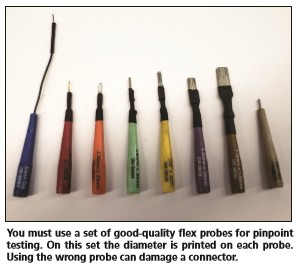
3.2. Test Leads and Probes
Quality test leads and probes are essential for making secure and accurate connections.
- Sharp Probes: For piercing insulation to access wires.
- Alligator Clips: For attaching to ground points and terminals.
- Extension Leads: For reaching difficult-to-access areas.
3.3. Wiring Diagrams
Wiring diagrams provide essential information about circuit layouts, component locations, and wiring colors. These diagrams are crucial for identifying test points and understanding circuit functionality.
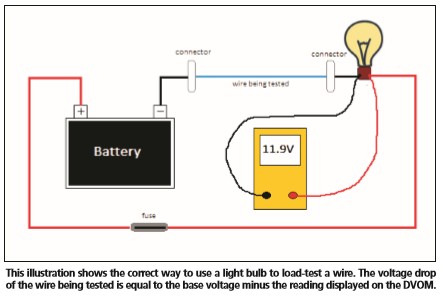
3.4. Load Tester
A load tester simulates the normal operating load of a circuit. This tool is particularly useful when voltage drop is suspected but not immediately apparent.
**3.5. Battery Charger
Maintaining a stable voltage source is crucial during voltage drop testing. A battery charger ensures that the battery voltage does not drop below 12V during testing.
4. Step-by-Step Guide to Performing Voltage Drop Testing
Follow these steps to perform voltage drop testing effectively:
4.1. Preparation
- Gather Information: Obtain the wiring diagram for the circuit being tested.
- Identify the Circuit: Understand the function and components of the circuit.
- Locate Test Points: Identify the points where voltage drop will be measured.
- Prepare Tools: Ensure your DMM, test leads, and other tools are in good working condition.
4.2. Setting Up the Test
- Connect the Circuit: Ensure the circuit is connected and in its normal operating state.
- Apply Load: Activate the circuit to apply the normal operating load. For example, turn on the headlights for a headlight circuit.
- Stabilize Voltage: Connect a battery charger to maintain a stable voltage source.
4.3. Performing the Voltage Drop Test
- Connect the DMM:
- Set the DMM to the DC voltage setting.
- Connect the red lead to the positive side of the circuit section being tested.
- Connect the black lead to the negative side of the circuit section being tested.
- Measure Voltage Drop:
- Read the voltage drop value on the DMM.
- Record the reading for analysis.
- Repeat Measurements:
- Repeat the measurement at different points along the circuit to isolate the area with excessive voltage drop.
4.4. Analyzing the Results
- Compare to Specifications: Compare the measured voltage drop to the manufacturer’s specifications. Generally, a voltage drop of more than 0.5V is considered excessive.
- Isolate the Fault:
- If the voltage drop is excessive, isolate the section of the circuit causing the problem.
- Check connections, wires, and components in that section.
- Repair the Fault:
- Repair or replace the faulty component or wiring.
- Clean corroded connections and ensure they are tight.
4.5. Verifying the Repair
- Re-test: After making repairs, re-test the circuit to ensure the voltage drop is within acceptable limits.
- Monitor: Monitor the circuit’s performance to ensure the issue is resolved.
5. Common Causes of Excessive Voltage Drop
Several factors can cause excessive voltage drop in a circuit:
5.1. Corroded Connections
Corrosion increases resistance at connections, leading to voltage drop. Clean and tighten corroded connections to restore proper conductivity.
5.2. Loose Connections
Loose connections create resistance due to poor contact between conductors. Ensure all connections are tight and secure.
5.3. Damaged Wires
Damaged or frayed wires reduce the effective cross-sectional area, increasing resistance. Replace damaged wires to ensure proper current flow.
5.4. Faulty Components
Internal faults in components like switches, relays, or motors can increase resistance and cause voltage drop. Test and replace faulty components.
5.5. Undersized Wires
Using wires that are too small for the current they need to carry can cause excessive voltage drop. Replace undersized wires with appropriately sized ones.
6. How Voltage Drop Testing Helps Diagnose Circuit-Related DTCs
Voltage drop testing is invaluable for diagnosing circuit-related DTCs by pinpointing the root cause of electrical issues. Here are some examples of how it can be used:
6.1. ABS Hydraulic Pump Motor Circuit Failure (C1095)
If a vehicle shows a DTC C1095 indicating an ABS hydraulic pump motor circuit failure, voltage drop testing can help identify excessive resistance in the power or ground circuits of the pump motor.
- Test Power Supply: Check the voltage drop between the battery and the pump motor’s power terminal.
- Test Ground Connection: Measure the voltage drop between the pump motor’s ground terminal and the vehicle chassis ground.
- Analyze Results: High voltage drop indicates a problem in the respective circuit, such as a corroded connector or damaged wire.
6.2. Fuel Injector Circuit Malfunction
For a fuel injector circuit malfunction, voltage drop testing can identify issues in the injector’s power or control circuits.
- Test Power Supply: Measure the voltage drop from the battery to the fuel injector’s power terminal.
- Test Control Circuit: Check the voltage drop in the control circuit while the injector is activated.
- Analyze Results: Excessive voltage drop can indicate a faulty injector, wiring issue, or ECM problem.
6.3. Headlight Circuit Problems
Headlight circuits are prone to voltage drop due to high current draw. Voltage drop testing can identify issues causing dim or flickering headlights.
- Test Power Supply: Check the voltage drop from the battery to the headlight.
- Test Ground Connection: Measure the voltage drop between the headlight’s ground and the chassis ground.
- Analyze Results: A high voltage drop indicates a problem in the headlight’s power or ground circuit, often due to corroded connections or undersized wires.
6.4. Sensor Circuit Issues
Many sensor-related DTCs can be traced back to voltage drop issues in the sensor’s power, ground, or signal circuits.
- Test Power Supply: Measure the voltage drop from the battery to the sensor’s power terminal.
- Test Ground Connection: Check the voltage drop between the sensor’s ground and the chassis ground.
- Test Signal Circuit: Measure the voltage drop in the signal circuit while the sensor is operating.
- Analyze Results: Excessive voltage drop can indicate a faulty sensor, wiring issue, or ECM problem.
7. Advanced Voltage Drop Testing Techniques
Beyond basic voltage drop testing, advanced techniques can provide more detailed insights into circuit performance:
7.1. Voltage Drop Across Switches and Relays
Measuring the voltage drop across switches and relays can identify contact resistance issues.
- Test Setup: Connect the DMM leads to the input and output terminals of the switch or relay.
- Activate Component: Activate the switch or relay.
- Measure Voltage Drop: Read the voltage drop value on the DMM.
- Analyze Results: High voltage drop indicates excessive contact resistance, necessitating replacement.
7.2. Voltage Drop Across Fuses and Circuit Breakers
Testing the voltage drop across fuses and circuit breakers can identify issues with their contacts or internal resistance.
- Test Setup: Connect the DMM leads to the input and output terminals of the fuse or circuit breaker.
- Apply Load: Apply the normal operating load to the circuit.
- Measure Voltage Drop: Read the voltage drop value on the DMM.
- Analyze Results: High voltage drop indicates a problem with the fuse or circuit breaker, necessitating replacement.
7.3. Using a Load Tester for Enhanced Diagnosis
A load tester simulates the normal operating load of a circuit, which can help uncover voltage drop issues that may not be apparent under no-load conditions.
- Test Setup: Connect the load tester in series with the circuit being tested.
- Apply Load: Activate the load tester to apply a controlled load.
- Measure Voltage Drop: Measure the voltage drop across the circuit section being tested.
- Analyze Results: Compare the voltage drop under load to the expected value to identify potential issues.
8. Real-World Examples of Voltage Drop Testing
To illustrate the effectiveness of voltage drop testing, here are some real-world examples:
8.1. Example 1: Diagnosing Dim Headlights
A customer complains about dim headlights on their Mercedes-Benz. A visual inspection reveals no obvious issues. Voltage drop testing is performed:
- Test Power Supply: The voltage drop from the battery to the headlight is measured at 1.2V.
- Test Ground Connection: The voltage drop between the headlight’s ground and the chassis ground is measured at 0.8V.
- Analysis: Both voltage drop values are excessive. The technician traces the high voltage drop in the power circuit to a corroded connector. The ground circuit issue is traced to a loose connection at the chassis ground point.
- Repair: The technician cleans and tightens the corroded connector and the loose ground connection.
- Re-test: After the repairs, the voltage drop in both circuits is within acceptable limits, and the headlights are now bright.
8.2. Example 2: Identifying an ABS Fault
A Mercedes-Benz displays an ABS warning light. Diagnostic trouble codes indicate a problem with the ABS pump motor circuit. Voltage drop testing is performed:
- Test Power Supply: The voltage drop from the battery to the ABS pump motor is measured at 0.9V.
- Test Ground Connection: The voltage drop between the ABS pump motor’s ground and the chassis ground is measured at 0.6V.
- Analysis: Both voltage drop values are high. The technician discovers a damaged wire in the power circuit and a corroded ground connection.
- Repair: The damaged wire is replaced, and the corroded ground connection is cleaned and tightened.
- Re-test: After the repairs, the voltage drop in both circuits is within acceptable limits, and the ABS system functions correctly.
9. Voltage Drop Testing Best Practices
To ensure accurate and reliable results, follow these best practices when performing voltage drop testing:
9.1. Use Quality Equipment
Invest in a high-quality DMM and test leads for accurate and reliable measurements.
9.2. Review Wiring Diagrams
Always consult wiring diagrams to understand the circuit layout and identify appropriate test points.
9.3. Ensure Proper Connections
Make sure all connections are clean, tight, and secure to avoid introducing additional resistance into the circuit.
9.4. Apply Load
Test the circuit under its normal operating load to accurately assess its performance.
9.5. Interpret Results Carefully
Compare measured voltage drop values to manufacturer’s specifications and consider the circuit’s specific requirements when interpreting results.
9.6. Verify Repairs
After making repairs, re-test the circuit to ensure the voltage drop is within acceptable limits.
10. The Role of MERCEDES-DIAGNOSTIC-TOOL.EDU.VN in Mastering Voltage Drop Testing
MERCEDES-DIAGNOSTIC-TOOL.EDU.VN provides valuable resources and support for mastering voltage drop testing on Mercedes-Benz vehicles.
10.1. Comprehensive Guides and Tutorials
Access detailed guides and step-by-step tutorials on performing voltage drop testing on various Mercedes-Benz models and systems.
10.2. Wiring Diagrams and Technical Data
Find wiring diagrams, technical specifications, and troubleshooting tips specific to Mercedes-Benz vehicles.
10.3. Expert Support and Consultation
Get expert advice and consultation from experienced Mercedes-Benz technicians.
10.4. Diagnostic Tools and Equipment
Explore recommendations for high-quality diagnostic tools and equipment suitable for voltage drop testing on Mercedes-Benz vehicles.
10.5. Community Forum and Knowledge Sharing
Engage with a community of Mercedes-Benz enthusiasts and technicians to share knowledge, ask questions, and learn from others’ experiences.
11. Integrating Voltage Drop Testing into Your Diagnostic Routine
Make voltage drop testing a routine part of your diagnostic process to improve accuracy and efficiency.
11.1. Initial Inspection
Begin with a thorough visual inspection of the circuit, looking for obvious signs of damage or corrosion.
11.2. DTC Analysis
Analyze diagnostic trouble codes to identify potential circuit-related issues.
11.3. Voltage Drop Testing
Perform voltage drop testing to pinpoint areas of excessive resistance.
11.4. Component Testing
Test individual components to identify internal faults.
11.5. Repair and Verification
Repair or replace faulty components and re-test the circuit to ensure proper operation.
12. Understanding Mercedes-Benz Specific Diagnostic Procedures
Mercedes-Benz vehicles often have specific diagnostic procedures and requirements. Familiarizing yourself with these can help streamline the diagnostic process.
12.1. Accessing Mercedes-Benz Diagnostic Software
Use Mercedes-Benz diagnostic software such as XENTRY or DAS to access detailed diagnostic information and perform advanced tests.
12.2. Utilizing Wiring Diagrams and Technical Bulletins
Refer to Mercedes-Benz wiring diagrams and technical service bulletins for accurate and up-to-date information.
12.3. Following Mercedes-Benz Testing Procedures
Adhere to Mercedes-Benz-specific testing procedures and guidelines to ensure accurate results.
13. Staying Updated with the Latest Diagnostic Technologies
The field of automotive diagnostics is constantly evolving. Staying updated with the latest technologies and techniques is essential for providing high-quality service.
13.1. Continuous Training and Education
Participate in ongoing training and education to learn about new diagnostic tools and techniques.
13.2. Industry Events and Conferences
Attend industry events and conferences to network with other professionals and stay informed about the latest trends.
13.3. Online Resources and Communities
Utilize online resources and communities to share knowledge and learn from others.
14. Common Mistakes to Avoid During Voltage Drop Testing
Avoiding common mistakes can help ensure accurate and reliable results.
14.1. Incorrect Meter Settings
Ensure the DMM is set to the correct voltage range and DC mode.
14.2. Poor Connections
Make sure all connections are clean, tight, and secure.
14.3. Testing Without Load
Always test the circuit under its normal operating load.
14.4. Ignoring Wiring Diagrams
Consult wiring diagrams to understand the circuit layout and identify appropriate test points.
14.5. Neglecting Ground Connections
Pay close attention to ground connections, as they are often a source of voltage drop issues.
15. FAQ About Voltage Drop Testing and Circuit-Related DTCs
1. What is voltage drop testing?
Voltage drop testing is a diagnostic method used to identify excessive resistance in an electrical circuit by measuring the voltage difference across a component or section while the circuit is energized and operating.
2. How does voltage drop testing help diagnose circuit-related DTCs?
It helps pinpoint the exact location of excessive resistance, leading to accurate diagnosis and efficient repairs of electrical issues causing DTCs.
3. What tools are needed for voltage drop testing?
Essential tools include a high-quality digital multimeter (DMM), test leads, wiring diagrams, a load tester, and a battery charger.
4. What are the common causes of excessive voltage drop?
Common causes include corroded connections, loose connections, damaged wires, faulty components, and undersized wires.
5. What is a normal voltage drop value?
Generally, a voltage drop of more than 0.5V is considered excessive, but it can vary depending on the circuit.
6. Can voltage drop testing be used on any vehicle?
Yes, voltage drop testing can be used on any vehicle to diagnose electrical circuit issues.
7. How do I interpret voltage drop test results?
Compare the measured voltage drop to the manufacturer’s specifications and consider the circuit’s specific requirements when interpreting results.
8. What is the difference between resistance testing and voltage drop testing?
Resistance testing is done with the circuit de-energized and measures the state of the circuit, while voltage drop testing is done with the circuit energized and measures its performance under load.
9. Why is it important to use a wiring diagram during voltage drop testing?
Wiring diagrams provide essential information about circuit layouts, component locations, and wiring colors, which are crucial for identifying test points and understanding circuit functionality.
10. How can I improve my voltage drop testing skills?
Practice regularly, stay updated with the latest diagnostic technologies, and consult expert resources and communities.
Voltage drop testing is an invaluable technique for diagnosing circuit-related DTCs and ensuring the proper functioning of electrical systems in Mercedes-Benz vehicles. By understanding the principles of voltage drop, using the right tools, following best practices, and leveraging the resources available at MERCEDES-DIAGNOSTIC-TOOL.EDU.VN, you can enhance your diagnostic skills and provide high-quality service to your customers.
Ready to take your Mercedes-Benz diagnostic skills to the next level? Contact us today at MERCEDES-DIAGNOSTIC-TOOL.EDU.VN, located at 789 Oak Avenue, Miami, FL 33101, United States, or via Whatsapp at +1 (641) 206-8880 for expert advice on diagnostic tools, unlocking hidden features, and repair guides. Let us help you keep your Mercedes-Benz running at its best.