OBD2 connectors are essential for accessing your vehicle’s self-diagnostic system, providing a standardized way to extract diagnostic trouble codes (DTCs) and real-time data. At MERCEDES-DIAGNOSTIC-TOOL.EDU.VN, we help you understand and utilize OBD2 connectors to diagnose and maintain your Mercedes-Benz effectively. By understanding their functions and applications, you can unlock valuable insights into your vehicle’s health, optimize performance, and save on costly repairs.
Contents
- 1. Understanding OBD2 Connectors
- 1.1. What is OBD2?
- 1.2. OBD2 History
- 1.3. Does My Car Support OBD2?
- 2. The Future of OBD2
- 2.1. Electric Vehicles and OBD2
- 2.2. The Debate Over Third-Party Access
- 3. OBD2 Standards and Protocols
- 3.1. OSI Model and Standards
- 3.2. The OBD2 Connector [SAE J1962]
- 3.3. OBD2 Connector – Type A vs. B
- 4. OBD2 and CAN Bus [ISO 15765-4]
- 4.1. OBD2 CAN Identifiers (11-bit, 29-bit)
- 4.2. OBD2 vs. Proprietary CAN Protocols
- 4.3. Bit-rate and ID Validation
- 4.4. Five Lower-Layer OBD2 Protocols
- 5. Transporting OBD2 Messages via ISO-TP [ISO 15765-2]
- 6. The OBD2 Diagnostic Message [SAE J1979, ISO 15031-5]
- 6.1. Example: OBD2 Request/Response
- 6.2. The 10 OBD2 Services (aka Modes)
- 6.3. OBD2 Parameter IDs (PID)
- 6.4. Tip: OBD2 PID Overview Tool
- 7. How to Log and Decode OBD2 Data
- 7.1. Testing Bit-rate, IDs & Supported PIDs
- 7.2. Configure OBD2 PID Requests
- 7.3. DBC Decode Raw OBD2 Data
- 8. OBD2 Multi-Frame Examples [ISO-TP]
- 8.1. Example 1: OBD2 Vehicle Identification Number (VIN)
- 8.2. Example 2: OBD2 Multi-PID Request (6x)
- 8.3. Example 3: OBD2 Diagnostic Trouble Codes (DTCs)
- 9. OBD2 Data Logging – Use Case Examples
- 9.1. Logging Data from Cars
- 9.2. Real-Time Car Diagnostics
- 9.3. Predictive Maintenance
- 9.4. Vehicle Blackbox Logger
- 10. Frequently Asked Questions (FAQ) About OBD2 Connectors
1. Understanding OBD2 Connectors
OBD2 connectors, or On-Board Diagnostics II connectors, are standardized interfaces used to access a vehicle’s self-diagnostic system. They provide a way to retrieve diagnostic trouble codes (DTCs) and real-time data, aiding in vehicle maintenance and diagnostics.
1.1. What is OBD2?
OBD2 is your vehicle’s built-in self-diagnostic system, a standardized protocol allowing extraction of diagnostic trouble codes (DTCs) and real-time data via the OBD2 connector. When the malfunction indicator light appears on your dashboard, it indicates an issue that can be diagnosed using an OBD2 scanner connected to the OBD2 16-pin connector. This enables mechanics to troubleshoot problems by sending requests and receiving responses containing data like speed, fuel level, and DTCs.
1.2. OBD2 History
OBD2 originates from California, where the California Air Resources Board (CARB) required OBD in all new cars from 1991+ for emission control purposes. The Society of Automotive Engineers (SAE) recommended the OBD2 standard, standardizing DTCs and the OBD connector across manufacturers (SAE J1962). The OBD2 standard was implemented in phases:
- 1996: Mandatory in the USA for cars/light trucks.
- 2001: Required in the EU for gasoline cars.
- 2003: Required in the EU for diesel cars (EOBD).
- 2005: Required in the US for medium-duty vehicles.
- 2008: US cars must use ISO 15765-4 (CAN) as OBD2 basis.
- 2010: Finally required in the US for heavy-duty vehicles.
1.3. Does My Car Support OBD2?
Almost all newer non-electric cars support OBD2, and most run on CAN bus. However, even if a 16-pin OBD2 connector is present in older cars, it may not support OBD2. To determine compliance, check where and when the car was bought new:
| Region | OBD2 Compliance Date |
|---|---|
| United States | 1996 |
| European Union | 2001 (Gasoline) |
| European Union | 2003 (Diesel) |
2. The Future of OBD2
OBD2 is evolving with alternatives like WWH-OBD and OBDonUDS, which enhance communication via the UDS protocol. OBD3, adding telematics to cars, aims to send vehicle identification numbers (VIN) and DTCs via WiFi to a central server for checks. While this offers convenience, surveillance concerns pose challenges.
2.1. Electric Vehicles and OBD2
Electric vehicles are generally not required to support OBD2 for emission control. Many modern EVs use OEM-specific UDS communication, making data decoding challenging unless reverse engineering is applied. Case studies for electric cars, including Tesla, Hyundai/Kia, Nissan, and VW/Skoda, showcase instances where decoding rules have been reverse-engineered.
2.2. The Debate Over Third-Party Access
The German car industry is looking to limit third-party access to OBD2 data, proposing to collect data in a central server instead. While this is argued to improve security by reducing the risk of car hacking, many view it as a commercial move to control automotive big data. This change could disrupt the market for third-party OBD2 services.
3. OBD2 Standards and Protocols
OBD2, a higher-layer protocol, specifies the OBD2 connector, lower-layer protocols, and parameter IDs (PID). Comparable to other CAN-based protocols like J1939, CANopen, and NMEA 2000, OBD2 standards can be displayed in a 7-layer OSI model.
3.1. OSI Model and Standards
The OBD2 standards cover various layers of the OSI model, with both SAE and ISO standards addressing specific aspects. SAE standards are primarily used in the USA, while ISO standards are common in the EU. Key standards include:
- SAE J1979 vs. ISO 15031-5 (Diagnostic Services)
- SAE J1962 vs. ISO 15031-3 (OBD Connector)
3.2. The OBD2 Connector [SAE J1962]
The 16-pin OBD2 connector, specified in SAE J1962 / ISO 15031-3, allows easy access to vehicle data. Key features of the connector:
- Located near the steering wheel, but may be hidden.
- Pin 16 provides battery power, even when the ignition is off.
- The OBD2 pinout depends on the communication protocol.
- CAN bus is the most common lower-layer protocol, typically connecting pins 6 (CAN-H) and 14 (CAN-L).
3.3. OBD2 Connector – Type A vs. B
You may encounter type A and type B OBD2 connectors. Type A is typically found in cars, while type B is common in medium and heavy-duty vehicles. The main differences are:
- Power Supply: 12V for type A and 24V for type B.
- Baud Rate: Cars typically use 500K, while heavy-duty vehicles often use 250K (but may support 500K).
- Physical Distinction: Type B has an interrupted groove in the middle.
A type B OBD2 adapter cable is compatible with both types A and B, while a type A cable will not fit into a type B socket.
4. OBD2 and CAN Bus [ISO 15765-4]
Since 2008, CAN bus has been the mandatory lower-layer protocol for OBD2 in all cars sold in the US, as per ISO 15765. ISO 15765-4 (Diagnostics over CAN or DoCAN) standardizes the CAN interface for test equipment, focusing on the physical, data link, and network layers:
- Bit-rate: 250K or 500K
- CAN IDs: 11-bit or 29-bit
- Specific CAN IDs: Used for OBD requests/responses
- Data Length: 8 bytes
- Adapter Cable Length: Max 5 meters
4.1. OBD2 CAN Identifiers (11-bit, 29-bit)
OBD2 communication involves request/response messages. In most cars, 11-bit CAN IDs are used, with the ‘Functional Addressing’ ID being 0x7DF. This asks all OBD2-compatible ECUs if they have data to report on the requested parameter. CAN IDs 0x7E0-0x7E7 can be used for ‘Physical Addressing’ requests from specific ECUs. ECUs respond with 11-bit IDs 0x7E8-0x7EF, with 0x7E8 (ECM, Engine Control Module) and 0x7E9 (TCM, Transmission Control Module) being the most common.
In some vehicles, extended 29-bit CAN identifiers are used, with the ‘Functional Addressing’ CAN ID being 0x18DB33F1. Responses are seen with CAN IDs 0x18DAF100 to 0x18DAF1FF, often shown in the J1939 PGN form as PGN 0xDA00 (55808).
4.2. OBD2 vs. Proprietary CAN Protocols
Your car’s ECUs do not rely on OBD2 to function; OEMs implement their own proprietary CAN protocols. These protocols are specific to the vehicle brand, model, and year, and interpreting this data is usually not possible without reverse engineering. If you connect a CAN bus data logger to your car’s OBD2 connector, you may see the OEM-specific CAN data, but many newer cars use a ‘gateway’ to block access and only enable OBD2 communication. Think of OBD2 as an ‘extra’ higher-layer protocol parallel to the OEM-specific protocol.
4.3. Bit-rate and ID Validation
OBD2 may use bit-rates of 250K or 500K and CAN ID lengths of 11-bit or 29-bit, resulting in four potential combinations. Modern cars commonly use 500K and 11-bit IDs, but external tools should systematically verify this. ISO 15765-4 provides recommendations for performing an initialization sequence to determine the correct combination. Newer versions consider vehicles may support OBD communication via OBDonUDS rather than OBDonEDS.
4.4. Five Lower-Layer OBD2 Protocols
While CAN is the primary lower-layer protocol for OBD2 today, older cars may use other protocols. These include:
- ISO 15765 (CAN bus): Mandatory in US cars since 2008.
- ISO14230-4 (KWP2000): Common in 2003+ cars, especially in Asia.
- ISO 9141-2: Used in EU, Chrysler & Asian cars in 2000-04.
- SAE J1850 (VPW): Mostly used in older GM cars.
- SAE J1850 (PWM): Mostly used in older Ford cars.
5. Transporting OBD2 Messages via ISO-TP [ISO 15765-2]
All OBD2 data is communicated on the CAN bus through the ISO-TP transport protocol (ISO 15765-2), enabling communication of payloads exceeding 8 bytes. This is necessary for extracting the Vehicle Identification Number (VIN) or Diagnostic Trouble Codes (DTCs). ISO 15765-2 facilitates segmentation, flow control, and reassembly. Often, OBD2 data fits in a single CAN frame, using a ‘Single Frame’ (SF) where the 1st data byte contains the payload length, leaving 7 bytes for OBD2-related communication.
6. The OBD2 Diagnostic Message [SAE J1979, ISO 15031-5]
An OBD2 message consists of an identifier, data length (PCI field), and data split into Mode, parameter ID (PID), and data bytes.
6.1. Example: OBD2 Request/Response
Consider a request/response for ‘Vehicle Speed.’ An external tool sends a request message to the car with CAN ID 0x7DF and two payload bytes: Mode 0x01 and PID 0x0D. The car responds via CAN ID 0x7E8 and three payload bytes, including the vehicle speed value in the 4th byte, 0x32 (50 in decimal form). Looking up the decoding rules for OBD2 PID 0x0D, we determine the physical value is 50 km/h.
6.2. The 10 OBD2 Services (aka Modes)
There are 10 OBD2 diagnostic services (or modes). Mode 0x01 shows current real-time data, while others are used to show/clear DTCs or show freeze-frame data. Vehicles do not have to support all OBD2 modes and may support OEM-specific modes. In OBD2 messages, the mode is in the 2nd byte. In the request, the mode is included directly (e.g., 0x01), while in the response, 0x40 is added to the mode (e.g., resulting in 0x41).
6.3. OBD2 Parameter IDs (PID)
Each OBD2 mode contains parameter IDs (PIDs). For example, mode 0x01 contains ~200 standardized PIDs with real-time data on speed, RPM, and fuel level. Vehicles do not have to support all PIDs in a mode, and most only support a small subset. If an emissions-related ECU supports any OBD2 services, it must support mode 0x01 PID 0x00. In response, the vehicle ECU informs whether it supports PIDs 0x01-0x20. PIDs 0x20, 0x40, …, 0xC0 can be used to determine support for the remaining mode 0x01 PIDs.
6.4. Tip: OBD2 PID Overview Tool
Scaling info for standard OBD2 PIDs can be found in the appendices of SAE J1979 and ISO 15031-5, allowing you to decode data into physical values. Use our OBD2 PID overview tool to construct OBD2 request frames and dynamically decode OBD2 responses.
7. How to Log and Decode OBD2 Data
Logging OBD2 data with the CANedge CAN bus data logger is an effective method. The CANedge allows you to configure custom CAN frames to be transmitted, enabling OBD2 logging. Connect the device to your vehicle using an OBD2-DB9 adapter cable.
7.1. Testing Bit-rate, IDs & Supported PIDs
Follow these steps to determine the bit-rate and IDs used by your vehicle, as described in ISO 15765-4:
- Send a CAN frame at 500K and check if successful (if not, try 250K).
- Use the identified bit-rate for subsequent communication.
- Send multiple ‘Supported PIDs’ requests and review the results.
- Based on response IDs, determine 11-bit vs. 29-bit.
- Based on response data, see what PIDs are supported.
Most 2008+ non-EV cars support 40-80 PIDs via 500K bit-rate, 11-bit CAN IDs, and the OBD2/OBDonEDS protocol.
7.2. Configure OBD2 PID Requests
Configure your transmit list with PIDs of interest, considering the following:
- CAN IDs: Shift to ‘Physical Addressing’ request IDs (e.g., 0x7E0) to avoid multiple responses.
- Spacing: Add 300-500 ms between each OBD2 request to prevent ECU overload.
- Battery Drain: Use triggers to stop transmitting when the vehicle is inactive.
- Filters: Add filters to only record OBD2 responses, especially if your vehicle outputs OEM-specific CAN data.
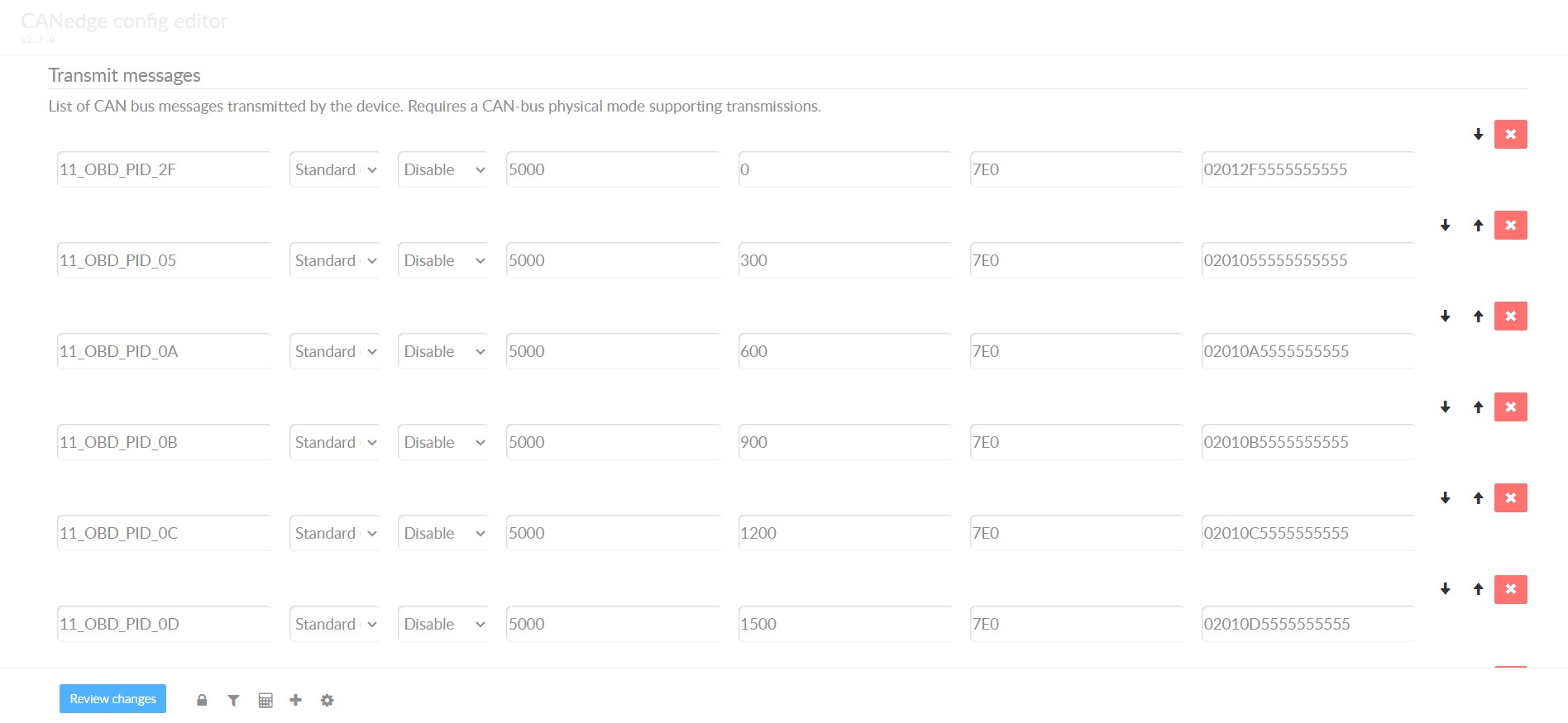 obd2-transmit-list-example-canedge
7.3. DBC Decode Raw OBD2 Data
To analyze and visualize your data, decode the raw OBD2 data into physical values (e.g., km/h or degC). The necessary decoding information is available in ISO 15031-5/SAE J1979. Use a free OBD2 DBC file to DBC decode raw OBD2 data in most CAN bus software tools. Decoding OBD2 data is more complex than regular CAN signals because different OBD2 PIDs are transported using the same CAN ID (e.g., 0x7E8). Leverage the CAN ID, OBD2 mode, and OBD2 PID to identify the signal.
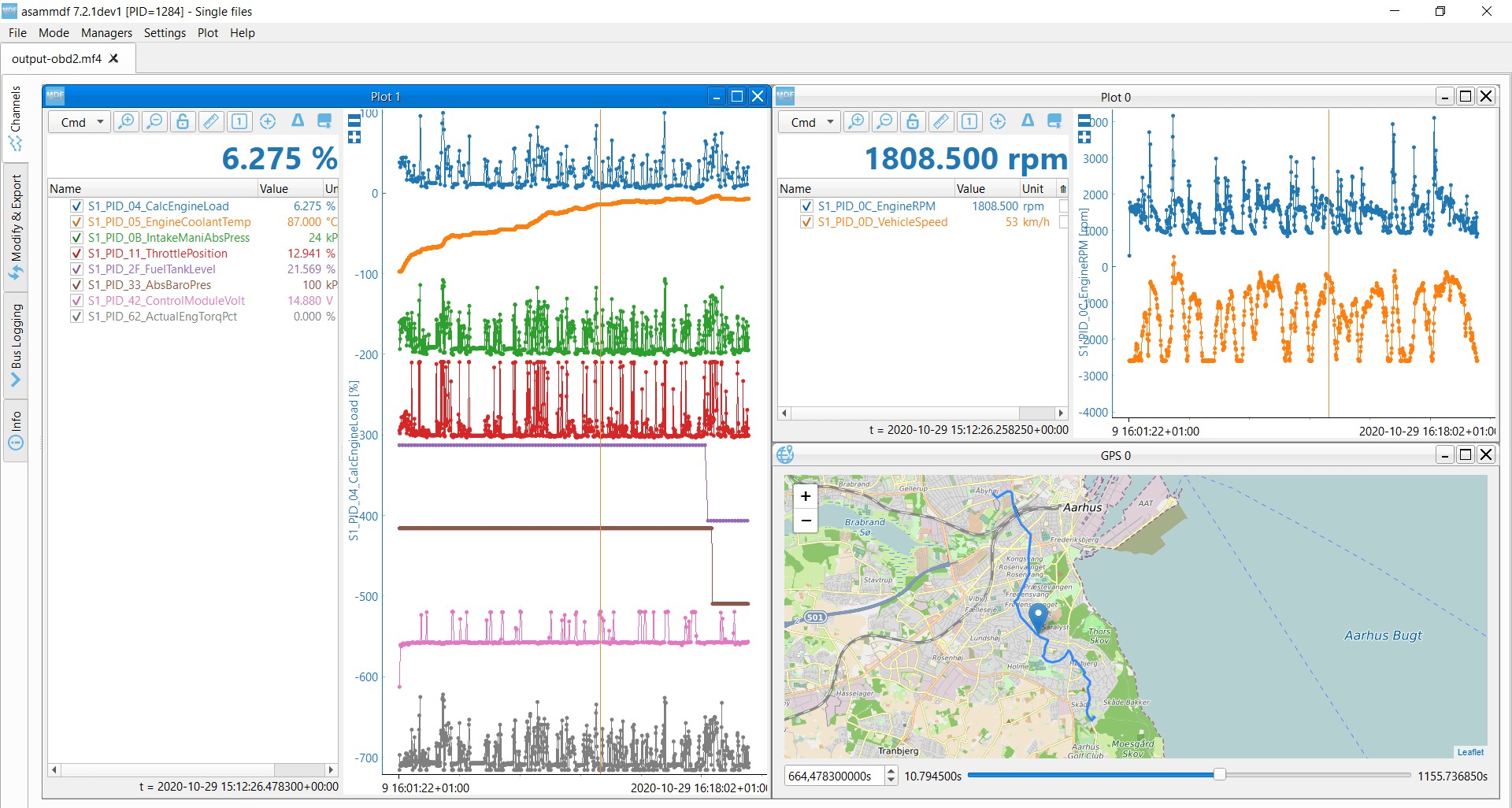 OBD2 data decoded visual plot asammdf CAN bus DBC file
8. OBD2 Multi-Frame Examples [ISO-TP]
All OBD2 data is communicated using the ISO-TP (transport protocol) as per ISO 15765-2. Multi-frame OBD2 communication requires flow control frames. This can be done by transmitting a static flow control frame 50 ms after the initial request frame. Additionally, multi-frame OBD2 responses require CAN software/API tools that support ISO-TP, like the CANedge MF4 decoders.
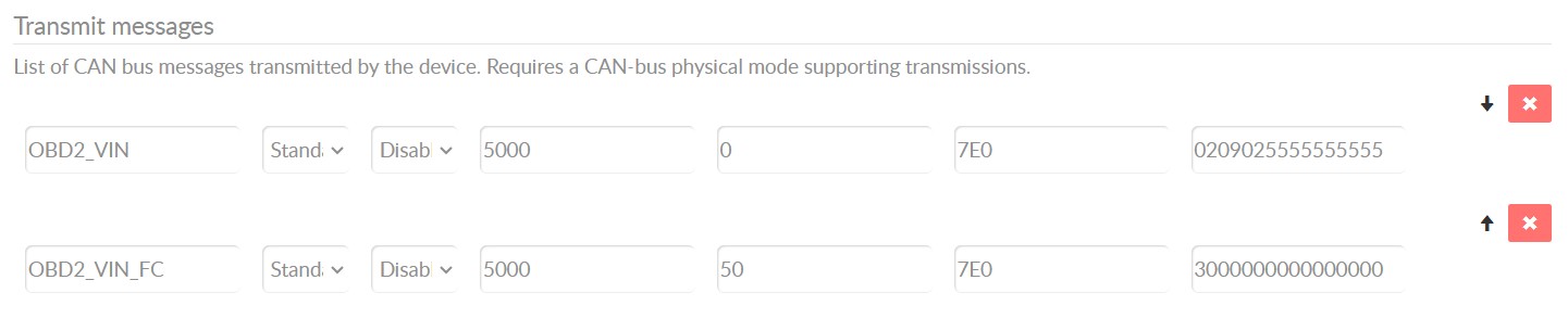 OBD2-multi-frame-request-message-vehicle-identification-number
8.1. Example 1: OBD2 Vehicle Identification Number (VIN)
Extracting the VIN using OBD2 requests involves mode 0x09 and PID 0x02.
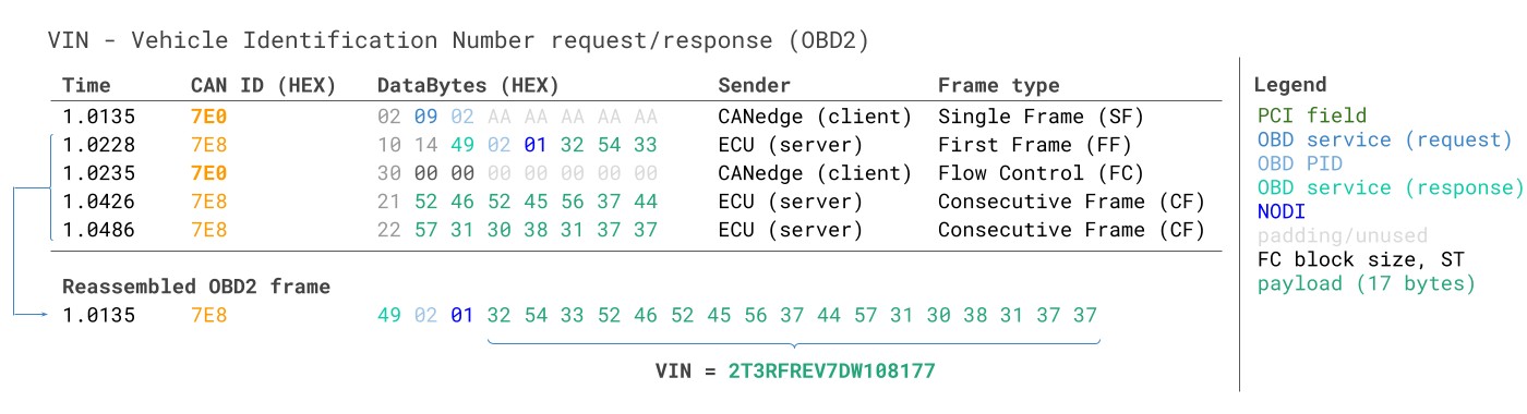 VIN Vehicle Identification Number OBD2 Example multi-frame
The tester tool sends a Single Frame request. The vehicle responds with a First Frame containing the PCI, length, mode, and PID, followed by the byte 0x01 (Number Of Data Items – NODI). The remaining 17 bytes equal the VIN, which can be translated from HEX to ASC.
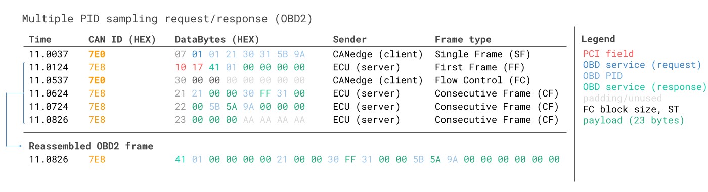
8.2. Example 2: OBD2 Multi-PID Request (6x)
External tools can request up to 6 mode 0x01 OBD2 PIDs in a single request frame. The ECU responds with data for supported PIDs, potentially across multiple frames as per ISO-TP.
 Requesting multiple PIDs in one request
8.3. Example 3: OBD2 Diagnostic Trouble Codes (DTCs)
Request emissions-related DTCs using mode 0x03. The ECU(s) respond with the number of DTCs stored, with each DTC taking up 2 data bytes. Multi-frame responses are necessary when more than 2 DTCs are stored. The 2-byte DTC value is split into two parts: the first 2 bits define the category, and the remaining 14 bits define a 4-digit code. Decoded DTC values can be looked up in OBD2 DTC lookup tools.
9. OBD2 Data Logging – Use Case Examples
OBD2 data from cars and light trucks can be used in various applications:
9.1. Logging Data from Cars
OBD2 data from cars can be used to reduce fuel costs, improve driving, test prototype parts, and for insurance purposes.
9.2. Real-Time Car Diagnostics
OBD2 interfaces can stream human-readable data in real-time for diagnosing vehicle issues.
9.3. Predictive Maintenance
Cars and light trucks can be monitored via IoT OBD2 loggers in the cloud to predict and avoid breakdowns.
9.4. Vehicle Blackbox Logger
An OBD2 logger can serve as a ‘blackbox’ for vehicles, providing data for disputes or diagnostics.
10. Frequently Asked Questions (FAQ) About OBD2 Connectors
1. What is an OBD2 connector?
An OBD2 connector is a standardized port in your vehicle that allows diagnostic tools to access the car’s computer system for troubleshooting and data retrieval.
2. Where is the OBD2 connector located in my car?
The OBD2 connector is typically located under the dashboard on the driver’s side. It may be near the steering column or inside the glove compartment.
3. What types of data can I access through the OBD2 connector?
You can access real-time data such as speed, engine RPM, fuel level, and diagnostic trouble codes (DTCs) indicating potential issues with the vehicle.
4. Can I use any OBD2 scanner with my Mercedes-Benz?
While OBD2 is a standardized protocol, some scanners may have limited compatibility or functionality with specific Mercedes-Benz models. It’s best to choose a scanner that is known to work well with Mercedes-Benz vehicles or consult with a professional at MERCEDES-DIAGNOSTIC-TOOL.EDU.VN.
5. How do I interpret the diagnostic trouble codes (DTCs) retrieved from the OBD2 connector?
DTCs are alphanumeric codes that provide information about the specific issue detected by the vehicle’s computer. You can use online OBD2 DTC lookup tools or consult a repair manual to understand the meaning of each code.
6. Is it safe to leave an OBD2 scanner plugged into the connector while driving?
Some OBD2 scanners are designed for continuous monitoring, while others are intended for temporary use during diagnostics. Check the scanner’s documentation to ensure it is safe to leave plugged in while driving to avoid potential battery drain or interference with the vehicle’s systems.
7. What is the difference between OBD2 and OBD1?
OBD1 was an earlier, less standardized version of onboard diagnostics. OBD2 is more comprehensive and standardized, providing more detailed information and compatibility across different vehicle makes and models.
8. Can I clear diagnostic trouble codes (DTCs) using an OBD2 scanner?
Yes, many OBD2 scanners have the capability to clear DTCs after the issue has been resolved. However, clearing the codes does not fix the underlying problem, and the codes may reappear if the issue persists.
9. Are there any risks associated with using an OBD2 scanner?
Using an OBD2 scanner is generally safe, but it’s important to follow the manufacturer’s instructions and avoid making changes to the vehicle’s systems without proper knowledge and expertise. Incorrect modifications can potentially damage the vehicle.
10. Where can I find reliable information and support for OBD2 diagnostics and Mercedes-Benz vehicles?
MERCEDES-DIAGNOSTIC-TOOL.EDU.VN offers comprehensive information, expert support, and diagnostic tools tailored for Mercedes-Benz vehicles. You can also consult repair manuals, online forums, and certified Mercedes-Benz technicians for assistance.
Do you have an OBD2 data logging use case? Reach out to MERCEDES-DIAGNOSTIC-TOOL.EDU.VN for expert assistance and free sparring! We are located at 789 Oak Avenue, Miami, FL 33101, United States. Contact us via Whatsapp at +1 (641) 206-8880 or visit our website MERCEDES-DIAGNOSTIC-TOOL.EDU.VN.
At MERCEDES-DIAGNOSTIC-TOOL.EDU.VN, we’re dedicated to providing you with the resources and support you need to effectively diagnose and maintain your Mercedes-Benz. Contact us today to learn more about how we can help you leverage the power of OBD2 connectors for optimal vehicle performance and longevity.