Unified Diagnostic Services (UDS) is a communication protocol used in automotive Electronic Control Units (ECUs) to enable diagnostics, firmware updates, routine testing and more but Are There Different DTC Formats For Electric Vehicles (EVs)? Yes, the DTC formats can vary in EVs due to the integration of new diagnostic parameters specific to electric powertrains; for comprehensive diagnostics and unlocking hidden features, turn to MERCEDES-DIAGNOSTIC-TOOL.EDU.VN. This article provides an overview of how to record EV State of Charge and Vehicle Identification Number (VIN).
Contents
- 1. What is the UDS Protocol?
- 2. UDS vs CAN Bus: Standards & OSI Model
- 2.1. Overview of UDS Standards & Concepts
- 2.1.1. ISO 14229-3 (UDSonCAN)
- 2.1.2. ISO 14229-2
- 2.1.3. ISO 15765-2 (ISO-TP)
- 2.1.4. ISO 11898-1 and ISO 11898-2
- 2.2. UDSonCAN vs DoCAN
- 3. UDS – No Standard Connector?
- 4. UDS Message Structure [ISO 14229-1/3]
- 4.1. Protocol Control Information (PCI)
- 4.2. UDS Service ID (SID)
- 4.3. UDS Sub Function Byte
- 4.3.1. Example: Service 0x19 Sub Functions
- 4.4. UDS ‘Request Data Parameters’ – incl. Data Identifier (DID)
- 4.4.1. Example: Service 0x22 DIDs
- 5. Positive vs. Negative UDS Responses [ISO 14229-1]
- 6. CAN ISO-TP – Transport Protocol [ISO 15765-2]
- 6.1. ISO-TP: Single-Frame Communication
- 6.2. ISO-TP: Multi-Frame Communication
- 7. UDS vs. OBD2 vs. WWH-OBD vs. OBDonUDS
- 7.1. What is WWH-OBD (ISO 27145)?
- 7.2. What is OBDonUDS (SAE J1979-2)?
- 8. How to Request/Record UDS Data
- 8.1. Can You Request UDS Data With a Data Logger?
- 8.2. Is UDS Standardized Across Cars and Trucks?
- 8.3. Should You Use UDS for Extracting Sensor Values?
1. What is the UDS Protocol?
Unified Diagnostic Services (UDS) is a communication protocol used in automotive Electronic Control Units (ECUs) to enable diagnostics, firmware updates, routine testing, and more. According to the ISO 14229 standard, the UDS protocol is standardized across both manufacturers and standards (such as CAN, KWP 2000, Ethernet, LIN). Further, UDS is today used in ECUs across all tier 1 Original Equipment Manufacturers (OEMs).
In practice, UDS communication is performed in a client-server relationship – with the client being a tester-tool and the server being a vehicle ECU. For example, you can connect a CAN bus interface to the OBD2 connector of a car and send UDS requests into the vehicle. Assuming the targeted ECU supports UDS services, it will respond accordingly.
In turn, this enables various use cases:
- Read/clear diagnostic trouble codes (DTC) for troubleshooting vehicle issues
- Extract parameter data values such as temperatures, state of charge, VIN etc
- Initiate diagnostic sessions to e.g. test safety-critical features
- Modify ECU behavior via resets, firmware flashing and settings modification
UDS is sometimes referred to as ‘vehicle manufacturer enhanced diagnostics‘ or ‘enhanced diagnostics‘ – more on this below.
2. UDS vs CAN Bus: Standards & OSI Model
To better understand UDS, we will look at how it relates to CAN bus and the OSI model.
As explained in our CAN bus tutorial, the Controller Area Network serves as a basis for communication. Specifically, CAN is described by a data-link layer and physical layer in the OSI model (as per ISO 11898). In contrast to CAN, UDS (ISO 14229) is a ‘higher layer protocol‘ and utilizes both the session layer (5th) and application layer (7th) in the OSI model as shown below:
2.1. Overview of UDS Standards & Concepts
UDS refers to a large number of standards/concepts, meaning it can be a bit overwhelming. To give you an overview, we provide a high level explanation of the most relevant ones below (with focus on CAN as the basis). We detail some of these further below.
In the following we provide a quick breakdown of each layer of the OSI model:
- Application: This is described by ISO 14229-1 (across the various serial data link layers). Further, separate ISO standards describe the UDS application layer for the various lower layer protocols – e.g. ISO 14229-3 for CAN bus (aka UDSonCAN)
- Presentation: This is vehicle manufacturer specific
- Session: This is described in ISO 14229-2
- Transport + Network: For CAN, ISO 15765-2 is used (aka ISO-TP)
- Data Link: In the case of CAN, this is described by ISO 11898-1
- Physical: In the case of CAN, this is described by ISO 11898-2
As illustrated, multiple standards other than CAN may be used as the basis for UDS communication – including FlexRay, Ethernet, LIN bus and K-line. In this tutorial we focus on CAN, which is also the most common lower layer protocol.
The ISO 14229-1 standard describes the application layer requirements for UDS (independent of what lower layer protocol is used). In particular, it outlines the following:
- Client-server communication flows (requests, responses, …)
- UDS services (as per the overview described previously)
- Positive responses and negative response codes (NRCs)
- Various definitions (e.g. DTCs, parameter data identifiers aka DIDs, …)
2.1.1. ISO 14229-3 (UDSonCAN)
The purpose of 14229-3 is to enable the implementation of Unified Diagnostic Services (UDS) on Controller Area Networks (CAN) – also known as UDSonCAN. This standard describes the application layer requirements for UDSonCAN.
This standard does not describe any implementation requirements for the in-vehicle CAN bus architecture. Instead, it focuses on some additional requirements/restrictions for UDS that are specific to UDSonCAN.
Specifically, 14229-3 outlines which UDS services have CAN specific requirements. The affected UDS services are ResponseOnEvent and ReadDataByPeriodicIdentifier, for which the CAN specific requirements are detailed in 14229-3. All other UDS services are implemented as per ISO 14229-1 and ISO 14229-2.
ISO 14229-3 also describes a set of mappings between ISO 14229-2 and ISO 15765-2 (ISO-TP) and describes requirements related to 11-bit and 29-bit CAN IDs when these are used for UDS and legislated OBD as per ISO 15765-4.
2.1.2. ISO 14229-2
This describes the session layer in the UDS OSI model. Specifically, it outlines service request/confirmation/indication primitives. These provide an interface for the implementation of UDS (ISO 14229-1) with any of the communication protocols (e.g. CAN).
2.1.3. ISO 15765-2 (ISO-TP)
For UDS on CAN, ISO 15765-2 describes how to communicate diagnostic requests and responses. In particular, the standard describes how to structure CAN frames to enable communication of multi-frame payloads. As this is a vital part of understanding UDS on CAN, we go into more depth in the next section.
2.1.4. ISO 11898-1 and ISO 11898-2
When UDS is based on CAN bus, the physical and data link layers are described in ISO 11898-1 and ISO 11898-2. When UDS is based on CAN, it can be compared to a higher layer protocol like J1939, OBD2, CANopen, NMEA 2000 etc. However, in contrast to these protocols, UDS could alternatively be based on other communication protocols like FlexRay, Ethernet, LIN etc.
2.2. UDSonCAN vs DoCAN
When talking about UDS based on CAN bus, you’ll often see two terms used: UDSonCAN (UDS on CAN bus) and DoCAN (Diagnostics on CAN bus). Some UDS tutorials use these terms interchangeably, which may cause confusion.
In ISO 14229-1 the terms are used as in our OSI model illustration. In other words, UDSonCAN is used to refer to ISO 14229-3, while DoCAN is used to refer to ISO 15765-2 aka ISO-TP.
However, part of the confusion may arise because ISO 14229-3 also provides an OSI model where DoCAN is both used in relation to ISO 15765-2 and as an overlay across OSI model layers 2 to 7. In ISO 14229-2, DoCAN is referred to as the communication protocol on which UDS (ISO 14229-1) is implemented. This is in sync with the illustration from ISO 14229-3. In this context, DoCAN can be viewed as a more over-arching term for the implementation of UDS on CAN, whereas UDSonCAN seems consistently to refer to ISO 14229-3 only.
UDS on CAN bus (UDSonCAN) is sometimes referred to through ISO 15765-3. However, this standard is now obsolete and has been replaced by ISO 14229-3.
3. UDS – No Standard Connector?
Unlike other higher-layer CAN protocols like OBD2, J1939 and ISOBUS, UDS does not specify a standard connector to be used for connecting external diagnostic equipment.
However, in practice the OBD2 connector (SAE J1962) is used in most vehicles. For example, electric vehicles from Nissan, Hyundai and VW support limited or no OBD2 communication, but do respond to UDS requests via the OBD2 connector.
4. UDS Message Structure [ISO 14229-1/3]
UDS is a request based protocol. In the illustration we’ve outlined an example of an UDS request frame (using CAN bus as basis):
A diagnostic UDS request on CAN contains various fields that we detail below:
4.1. Protocol Control Information (PCI)
The PCI field is not per se related to the UDS request itself, but is required for diagnostic UDS requests made on CAN bus and is related to ISO-TP (ISO 15765-2), as will be detailed below. The example illustration is a ‘Single Frame’ ISO-TP CAN message.
4.2. UDS Service ID (SID)
The use cases outlined above relate to different UDS services. When you wish to utilize a specific UDS service, the UDS request message should contain the UDS Service Identifier (SID) in the data payload. Note that the identifiers are split between request SIDs (e.g. 0x22) and response SIDs (e.g. 0x62). As in OBD2, the response SIDs generally add 0x40 to the request SIDs.
See also the overview of all standardized UDS services and SIDs. We will mainly focus on UDS service 0x22 in this article, which is used to read data (e.g. speed, SoC, temperature, VIN) from an ECU.
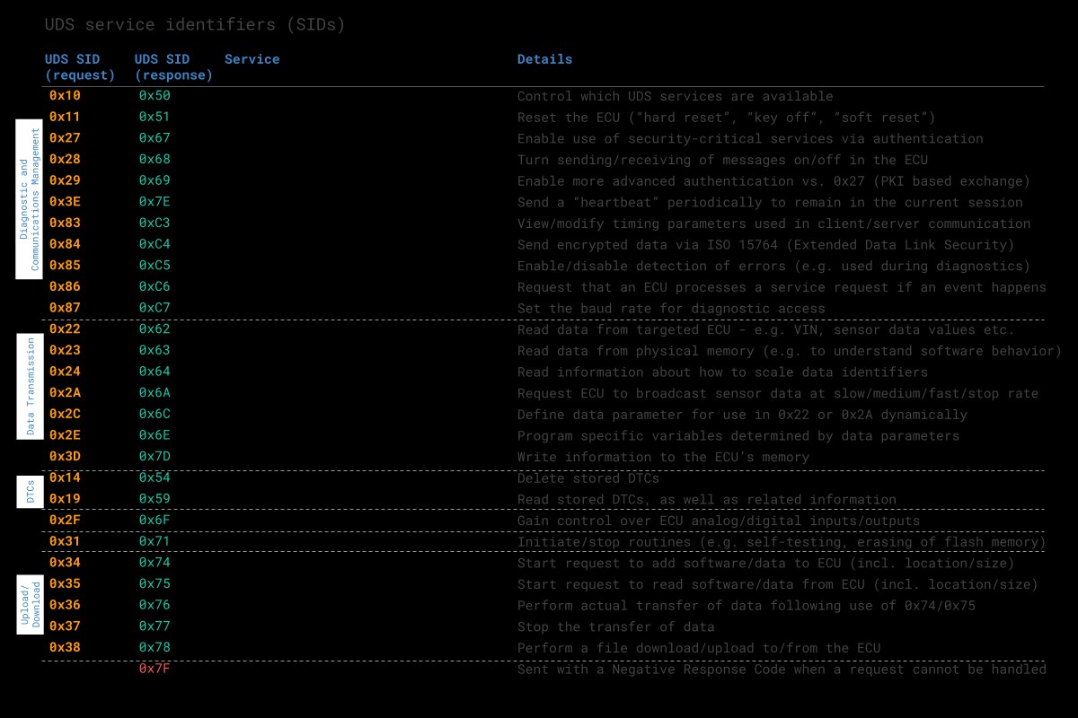 UDS Sevices Table Overview
The standardized UDS services shown above are in practice a subset of a larger set of diagnostic services – see below overview. Note here that the SIDs 0x00 to 0x0F are reserved for legislated OBD services (more on this later).
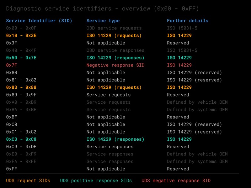 Vehicle Diagnostic Services UDS OBD ISO 14229
As evident, UDS enables extensive control over the vehicle ECUs. For security reasons, critical UDS services are therefore restricted through an authentication process. Basically, an ECU will send a ‘seed’ to a tester, who in turn must produce a ‘key’ to gain access to security-critical services. To retain this access, the tester needs to send a ‘tester present’ message periodically.
In practice, this authentication process enables vehicle manufactures to restrict UDS access for aftermarket users and ensure that only designated tools will be able to utilize the security-critical UDS services.
Note that the switching between authentication levels is done through diagnostic session control, which is one of the UDS services available. Vehicle manufactures can decide which sessions are supported, though they must always support the ‘default session’ (i.e. which does not involve any authentication). With that said, they decide what services are supported within the default session as well. If a tester tool switches to a non-default session, it must send a ‘tester present’ message periodically to avoid being returned to the default session.
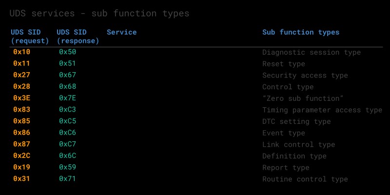 UDS Sub Function Byte Table Overview
4.3. UDS Sub Function Byte
The sub function byte is used in some UDS request frames as outlined below. Note, however, that in some UDS services, like 0x22, the sub function byte is not used.
Generally, when a request is sent to an ECU, the ECU may respond positively or negatively. In case the response is positive, the tester may want to suppress the response (as it may be irrelevant). This is done by setting the 1st bit to 1 in the sub function byte. Negative responses cannot be suppressed.
The remaining 7 bits can be used to define up to 128 sub function values.
4.3.1. Example: Service 0x19 Sub Functions
When reading DTC information via SID 0x19 (Read Diagnostic Information), the sub function can be used to control the report type (as per the table).
For example, sub function byte 0x02 lets you read DTCs via a status mask. In this case, the sub function byte is followed by a 1-byte parameter called DTC Status Mask to provide further information regarding the request (more on this below). Another common example is sub function byte 0x42, used in reading DTCs via WWH-OBD. In this case, 3 additional bytes are provided to configure the request (see also our trace example later in this article).
4.4. UDS ‘Request Data Parameters’ – incl. Data Identifier (DID)
In most UDS request services, various types of request data parameters are used to provide further configuration of a request beyond the SID and optional sub function byte.
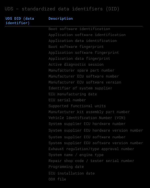 UDS Standard Data Identifiers DID 0x22
4.4.1. Example: Service 0x22 DIDs
An important example is service 0x22 (Read Data by Identifier). This service uses a Data Identifier (DID), which is a 2-byte value between 0 and 65535 (0xFFFF). The DID serves as a parameter identifier for both requests/responses (similar to how the parameter identifier, or PID, is used in OBD2). Notice that service 0x22 does not use a sub function byte.
For example, a request for reading data via a single DID in UDS over CAN would include the PCI field, the UDS service 0x22 and the 2-byte DID. Alternatively, one can request data for additional DIDs by adding them after the initial DID in the request.
We will look further into this in the section on how to record and decode UDS communication.
Data Identifiers can be proprietary and only known by OEMs, though some DIDs are standardized. This is for example the case for the WWH-OBD DIDs (more on this later) and the Vehicle Identification Number (VIN) is 0xF190. See the separate table for a list of standardized DIDs across UDS.
5. Positive vs. Negative UDS Responses [ISO 14229-1]
When an ECU responds positively to an UDS request, the response frame is structured with similar elements as the request frame. For example, a ‘positive’ response to a service 0x22 request will contain the response SID 0x62 (0x22 + 0x40) and the 2-byte DID, followed by the actual data payload for the requested DID. Generally, the structure of a positive UDS response message depends on the service.
However, in some cases an ECU may provide a negative response to an UDS request – for example if the service is not supported. A negative response is structured as in below CAN frame example:
The negative response frame can be broken down as follows:
- The 1st byte is the PCI field (ISO-TP Single Frame)
- The 2nd byte is the Negative Response Code SID, 0x7F
- The 3rd byte is the SID of the rejected request
- The 4th byte is the Negative Response Code (NRC)
In the negative UDS response, the NRC provides information regarding the cause of the rejection as per the table. In this example, the frame implies that a request was made using SID 0x22 (to read data by identifier), but that it failed due to an invalid message format or length.
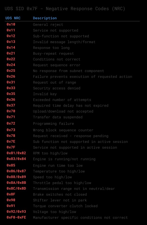 UDS NRC Response Code Table Negative Responses
6. CAN ISO-TP – Transport Protocol [ISO 15765-2]
When implementing diagnostics on CAN, one challenge is the size of the CAN frame payload: For Classical CAN frames, this is limited to 8 bytes and for CAN FD the payload is limited to 64 bytes. Vehicle diagnostics often involves communication of far larger payloads.
ISO 15765-2 was established to solve the challenge of large payloads for CAN based vehicle diagnostics.
The standard specifies a transport protocol and network layer services for use in CAN based vehicle networks. The most common use cases include UDS (ISO 14229-1), OBD (SAE J1979, ISO 15031-5) and world-wide harmonized OBD aka WWH-OBD (ISO 27145).
The ISO-TP standard outlines how to communicate CAN data payloads up to 4095 bytes through segmentation, flow control and reassembly. ISO-TP defines specific CAN frames for enabling this communication as shown below:
The flow control frame is used to ‘configure’ the subsequent communication. It can be constructed as below:
A few comments:
-
In the simplest case, the FC payload can be set to 30 00 00 00 00 00 00 00 (all remaining frames to be sent without delay)
-
Alternatively, one can decide to perform more granular control over the communication by e.g. alternating between the Wait and Continue commands, as well as specifying a specific separation time (in milliseconds) between frames
-
The ISO-TP frame type can be identified from the first nibble of the first byte (0x0, 0x1, 0x2, 0x3)
-
The total frame size can be up to 4095 bytes (0xFFF) as evident from the FF frame
-
The CF index runs from 1 to 15 (0xF) and is then reset if more data is to be sent
-
Padding (e.g. 0x00, 0xAA, …) is used to ensure the frame payloads equal 8 bytes in length
Below we outline how the ISO-TP protocol works for single-frame and multi-frame communication:
6.1. ISO-TP: Single-Frame Communication
In vehicle diagnostics, communication is initiated by a tester tool sending a request. This request frame is a Single Frame (SF).
In the simplest case, a tester tool sends a Single Frame to request data from an ECU. If the response can be contained in a 7-byte payload, the ECU provides a Single Frame response.
6.2. ISO-TP: Multi-Frame Communication
When the payload exceeds 7 bytes, it needs to be split across multiple CAN frames.
As before, a tester sends a Single Frame (SF) request to an ECU (sender). However, in this case the response exceeds 7 bytes.
Because of this, the ECU sends a First Frame (FF) that contains information on the total packet length (8 to 4095 bytes) as well as the initial chunk of data.
When the tester receives the FF, it will send a Flow Control (FC) frame, which tells the ECU how the rest of the data transfer should be transmitted.
Following this, the ECU will send Consecutive Frames (CF) that contain the remaining data payload.
ISO-TP plays an important role in most CAN based diagnostics protocols. Before we show practical examples of such communication flows, it is useful to get an overview of the most common vehicle diagnostic protocols.
7. UDS vs. OBD2 vs. WWH-OBD vs. OBDonUDS
A common question is how UDS relates to On-Board Diagnostics (OBD2), World-Wide Harmonized OBD (WWH-OBD) and OBDonUDS. To understand this, it is important to first note the following:
OBD (On-Board Diagnostics) is today implemented in different ways across countries and vehicles.
This is illustrated via the below OSI model comprising CAN based vehicle diagnostic protocols in use today:
Let’s look at each diagnostic protocol:
- ISO OBD (or EOBD) refers to the OBD protocol specification legislated for use in EU cars, while SAE OBD refers to the OBD protocol specification legislated for use in US. The two are technically equivalent and hence often referred to simply as OBD or OBD2
- HD OBD (SAE J1939) typically refers to heavy duty OBD and is commonly implemented through the J1939 protocol in both US and EU produced vehicles with J1939-73 specifying diagnostic messages
- UDS (ISO 14229) has been implemented by vehicle manufacturers to serve the need for richer diagnostics data/functionality – beyond the limits of the emissions-focused OBD protocols. It is implemented in most ECUs today, across markets and vehicle types – though in itself, UDS does not offer the necessary standardization required to serve as an alternative to OBD
- WWH-OBD (and/or possibly OBDonUDS) provide an updated version of OBD2 for emissions-related diagnostics – based on UDS
To understand UDS, it is useful to better understand WWH-OBD and OBDonUDS:
7.1. What is WWH-OBD (ISO 27145)?
WWH-OBD is a global standard for vehicle diagnostics, developed by the UN under the Global Technical Regulations (GTR) mandate. It aims to provide a single, future-proof alternative to the existing OBD protocols (ISO OBD, SAE OBD, HD OBD). Further, WWH-OBD is based on UDS in order to suit the enhanced diagnostics functionality already deployed by most automotive OEMs today.
Moving from OBD2 to WWH-OBD will involve a number of benefits, primarily derived from using the UDS protocol as the basis.
First of all, the data richness can be increased. OBD2 parameter identifiers (PID) are limited to 1 byte, restricting the number of unique data types to 255, while the UDS data identifier (DID) is 2 bytes, enabling 65535 parameters.
For diagnostic trouble codes (DTCs), OBD2 would allow for 2-byte DTCs. Here, WWH-OBD allows for ‘extended DTCs’ of 3 bytes. This allows for grouping DTCs by 2-byte types and using the 3rd byte as a failure mode indicator to specify the DTC sub type.
Further, WWH-OBD enables a classification of DTCs based on how severe an issue is in regards to the exhaust emissions quality.
WWH-OBD also seeks to take potential future requirements into account by allowing for the Internet Protocol (IP) to be used as an alternative to CAN, meaning that UDSonIP will also be possible in future implementations of WWH-OBD. One potential benefit from this will be the ability to one day perform remote diagnostics through the same protocol.
The intent of WWH-OBD is to serve as a global standard, across all markets and across all vehicle types (cars, trucks, buses, …). Further, the aim is to potentially expand the standardized functionality beyond just emissions-control.
In practice, WWH-OBD has been required in EU since 2014 for newly developed heavy duty vehicles (as per the Euro-VI standards). Note in this case that HD OBD (as per J1939) remains allowed in these vehicles.
Beyond this, however, the roll-out of WWH-OBD has been limited. One challenge is that WWH-OBD is currently not accepted by EPA/CARB in USA. However, recently OBDonUDS (SAE J1979-2) is being adopted in US.
7.2. What is OBDonUDS (SAE J1979-2)?
Similar to how OBD2 has been split into ‘SAE OBD’ (SAE J1979) for US and ‘ISO OBD’ (ISO 15031) for EU, the ‘next generation’ of OBD2 may again be regionally split.
Specifically, WWH-OBD (ISO 27145) has been adopted in EU for heavy duty vehicles already – but not yet in the US. Instead, it has recently been decided to adopt OBD on UDS in US vehicles in the form of the SAE J1979-2 standard, which serves as an update to the SAE J1979. The new SAE J1979-2 standard is also referred to as OBDonUDS. The aim is to initiate a transition phase starting in 2023, where ECUs are allowed to support either OBD2 or OBDonUDS. From 2027, OBDonUDS will be a mandatory requirement for all vehicles produced in the US.
To recap, WWH-OBD and OBDonUDS both serve as possible solutions for creating a ‘next generation’ protocol for emissions-related on-board diagnostics. It remains to be seen if the two will exist in parallel (like ISO/SAE OBD), or if one of the protocols will become the de facto standard across both US, EU and beyond.
In either case, the basis for emissions-related diagnostics will be UDS, which will serve to simplify ECU programming as the emissions-related diagnostics can increasingly be implemented within the same UDS based structure as the manufacturer specific enhanced diagnostics.
The CAN Calibration Protocol (CCP) and the Universal Measurement and Calibration Protocol (XCP) on CAN are CAN based higher layer protocols. These are typically used by automotive OEM engineers in early-stage prototype development, enabling measurement and calibration of ECUs. For further comparison vs. UDS, see our intro to CCP/XCP on CAN.
8. How to Request/Record UDS Data
We have now gone through the basics of UDS and ISO-TP.
With this in place, we can provide some concrete guidance on how you can work with UDS data in practice. In particular, we will focus on how UDS can be used to log various data parameters – like state of charge (SoC) in electric vehicles.
Before the examples, we cover frequently asked questions on UDS data logging below:
8.1. Can You Request UDS Data With a Data Logger?
Yes, as we’ll show further below, the CANedge can be configured to request UDS data. Effectively, the device can be configured to transmit up to 64 custom CAN frames as periodic or single shot frames. You can control the CAN ID, CAN data payload, period time and delay.
For single-frame UDS communication, you simply configure the CANedge with the request frame, which will trigger a single response frame from the ECU.
For multi-frame communication, you can again configure the CANedge with a request frame and then add the Flow Control frame as a separate frame to be transmitted X milliseconds after the request frame. By adjusting the timing, you can set this up so that the Flow Control is sent after the ECU has sent the First Frame response.
Note that the CANedge will record the UDS responses as raw CAN frames. You can then process and decode this data via your preferred software (e.g. Vector tools, Python or the MF4 decoders).
A common use case for recording UDS data via ‘standalone’ data loggers will be to acquire diagnostic trouble code values, e.g. for use in diagnosing issues.
In addition to the trouble codes, UDS lets you request the ‘current value’ of various sensors related to each ECU. This allows e.g. OEM engineers, vehicle fleet managers, researchers etc. to collect data of interest such as speed, RPM, state of charge, temperatures etc. from the vehicle (assuming they know how to request/decode the data).
Beyond the above, UDS can of course also be used for more low-level control of ECUs, e.g. resets and flashing of firmware, though such use cases are more commonly performed using a CAN bus interface, rather than a standalone device.
8.2. Is UDS Standardized Across Cars and Trucks?
Importantly, UDS is a manufacturer specific diagnostic protocol.
In other words, while UDS provides a standardized structure for diagnostic communication, the actual ‘content” of the communication remains proprietary and is in most cases only known to the manufacturer of a specific vehicle/ECU.
For example, UDS standardizes how to request parameter data from an ECU via the ‘Read Data By Identifier” service (0x22). But it does not specify a list of standardized identifiers and interpretation rules.
With that said, vehicles that support WWH-OBD or OBDonUDS may support some of the usual OBD2 PIDs like speed, RPM etc via the usual PID values – but with a prefix of 0xF4 as shown in Example 1 below.
Generally, only the manufacturer (OEM) will know how to request proprietary parameters via UDS – and how to interpret the result. Of course, one exception to this rule is cases where companies or individuals successfully reverse engineer the information. Engaging in such reverse engineering is a very difficult task, but you can sometimes find public information and DBC files where others have done this exercise. Our intro to DBC files contain a list of public DBC/decoding databases.
Because of the proprietary nature of UDS communication, it is typically most relevant to automotive engineers working at OEMs. Tools like the CANedge CAN bus data logger allow these users to record raw CAN traffic from a vehicle – while at the same time requesting diagnostic trouble codes and specific parameter values via UDS.
Further, some after market users like vehicle fleet managers and even private persons can benefit from UDS assuming they are able to identify the reverse engineered information required to request and decode the UDS parameters of interest.
Logging UDS data will also become increasingly relevant assuming WWH-OBD gets rolled out as expected. Already today, WWH-OBD is used in EU heavy duty vehicles produced after 2014, meaning UDS communication will be relevant for use cases related to on-board diagnostics in these vehicles.
8.3. Should You Use UDS for Extracting Sensor Values?
If you’re looking to request UDS-based diagnostic trouble codes (DTC), you’ll of course have to use UDS communication for this purpose. However, if your aim is to record current sensor values it is less clear.
Typically, data parameters of interest for e.g. vehicle telematics (speed, state of charge etc) will already be communicated between ECUs on the CAN bus in the form of raw CAN frames – without the need for a diagnostic tool requesting this information. That is because ECUs rely on communicating this information as part of their operation (as explained in our intro to CAN bus).
If you have direct access to the CAN bus, it would thus appear easier to simply log this raw CAN traffic and process it. If you are the vehicle manufacturer, you will know how to interpret this raw CAN