DTCs are instrumental in pinpointing issues in complex systems like variable valve timing (VVT), exemplified by codes like P0011 and P0014, and at MERCEDES-DIAGNOSTIC-TOOL.EDU.VN, we help you decipher these codes for efficient diagnosis and repair. By understanding how these codes relate to the VVT system, you can streamline your diagnostic process, saving time and resources. Use diagnostic tools, scan tool and data analysis for the process.
Contents
- 1. Understanding Variable Valve Timing (VVT) Systems
- 1.1. What is Camshaft Phasing?
- 1.2. Benefits of Camshaft Phasing
- 1.3. Camshaft Phasing Examples on the QR25 Engine
- 2. Essential Sensors in VVT Systems
- 2.1. Crankshaft Position Sensor (POS)
- 2.2. Camshaft Position Sensor (PHASE)
- 2.3. Exhaust Valve Timing Control Position Sensor
- 2.4. Solenoids in VVT Systems
- 3. How DTCs Help Pinpoint VVT Issues
- 3.1. Common VVT-Related DTCs
- 3.2. Initial Steps in DTC Diagnosis
- 3.3. Addressing Multiple DTCs
- 4. Detailed Diagnostic Procedures for Specific DTCs
- 4.1. Diagnosing P0643: Sensor Power Supply
- 4.1.1. Understanding the Issue
- 4.1.2. Diagnostic Steps
- 4.2. Diagnosing P0075 & P0078: Solenoid Circuit Issues
- 4.2.1. Diagnostic Steps
- 4.3. Diagnosing P0011, P052A, P052B, & P0014: Camshaft Angle Issues
- 4.3.1. Possible Causes
- 4.3.2. Diagnostic Steps
- 5. Advanced Diagnostic Techniques
- 5.1. Using Oscilloscopes for Sensor Analysis
- 5.2. Checking Static Timing
- 5.3. Lubrication Circuit Inspection
- 6. Addressing Intermittent Issues
- 6.1. Intermittent Incident Diagnosis
- 6.2. Real-World Examples
- 7. Importance of Following Service Manual Procedures
- 7.1. Example: Replacing VVT Components
- 8. Benefits of Using MERCEDES-DIAGNOSTIC-TOOL.EDU.VN
- 8.1. Expert Guidance and Support
- 8.2. Comprehensive Diagnostic Tools
- 8.3. Real-Time Data Monitoring
- 8.4. Addressing Complex Issues
- 9. Staying Updated with the Latest VVT Technologies
- 9.1. Continuous Learning and Training
- 9.2. Access to Updated Information
- 10. Call to Action
- 11. FAQs About VVT Systems and DTCs
- 11.1. What is Variable Valve Timing (VVT)?
- 11.2. How does VVT improve engine performance?
- 11.3. What are common symptoms of VVT problems?
- 11.4. What is the meaning of DTC P0011?
- 11.5. What is the meaning of DTC P0014?
- 11.6. Can low oil level cause VVT problems?
- 11.7. How do I diagnose VVT problems?
- 11.8. What tools are needed to diagnose VVT issues?
- 11.9. How often should I inspect my VVT system?
- 11.10. Can I fix VVT problems myself?
Intended search of the user:
- How to diagnose P0011 and P0014 codes
- Variable Valve Timing (VVT) system explained
- Meaning of DTCs in Mercedes-Benz vehicles
- How to fix camshaft timing issues
- Common problems with Nissan QR25 engine
1. Understanding Variable Valve Timing (VVT) Systems
Variable Valve Timing (VVT) systems are designed to optimize engine performance, reduce emissions, and improve fuel efficiency by adjusting the timing of the intake and exhaust valves. By varying valve timing, the engine can adapt to different driving conditions, providing optimal performance across a wide range of engine speeds and loads.
1.1. What is Camshaft Phasing?
Camshaft phasing involves changing the timing of the camshafts relative to the crankshaft and to each other, as explained by Nissan TechNews. This adjustment does not alter the duration or lift of valve opening but optimizes engine performance.
1.2. Benefits of Camshaft Phasing
Camshaft phasing offers several benefits:
- Enhanced Power and Torque: Maximizes engine power at high RPM while maintaining drivability at low RPM.
- Reduced Emissions: Controls the amount of exhaust gas remaining in the cylinder.
- Improved Fuel Efficiency: Reduces pumping losses.
1.3. Camshaft Phasing Examples on the QR25 Engine
The QR25 engine demonstrates different camshaft phasing scenarios:
- Minimum Phasing (Static Timing): Occurs when the Variable Camshaft Timing (VTC) system is inactive. The intake valve opens 5° after Top Dead Center (TDC), and the exhaust valve closes 3° after TDC.
- Maximum Phasing: Occurs when the VTC system is active. Intake valve timing is advanced, and exhaust valve timing is retarded, increasing power under high load by improving flow through the combustion chamber.
- Intermediate Phasing: Used during cold starts to reduce emissions. The intake valve opens 5° before TDC and closes 59° after Bottom Dead Center (BDC).
2. Essential Sensors in VVT Systems
The Engine Control Module (ECM) relies on several sensors to monitor and control variable valve timing accurately. These sensors provide crucial data about the engine’s position, speed, and valve timing, enabling the ECM to make precise adjustments.
2.1. Crankshaft Position Sensor (POS)
The Crankshaft Position Sensor (POS) is mounted near the engine oil pan and faces a signal plate on the crankshaft. This sensor detects crankshaft speed, position, and any fluctuations.
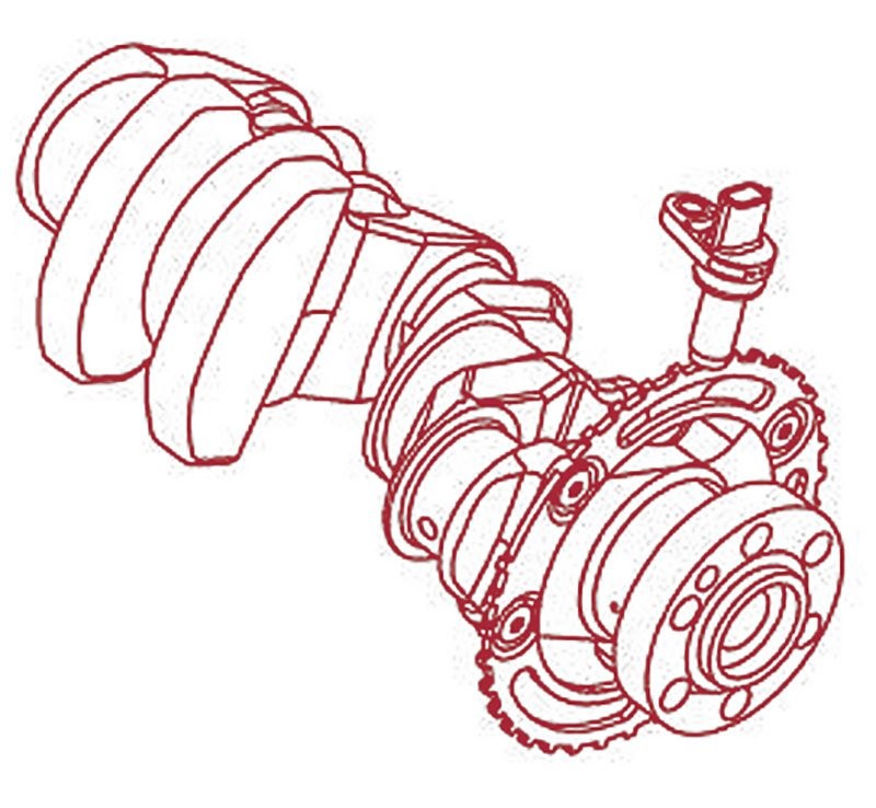 POS is oriented facing the signal plate on the rear of the crankshaft.
According to Bosch Automotive Handbook, the POS is critical for determining engine speed and position by monitoring the frequency and location of gaps in the signal plate.
2.2. Camshaft Position Sensor (PHASE)
The Camshaft Position Sensor (PHASE) is mounted on the camshaft position sensor bracket, located near the rocker cover, facing a signal plate on the intake camshaft. It identifies cylinders and produces a unique pulse for each cylinder.
 The PHASE is mounted facing the signal plate on the intake camshaft.
Failure of this sensor can lead to hard starts, rough idling, or misfires, as noted in the Nissan TechNews article.
2.3. Exhaust Valve Timing Control Position Sensor
This Hall Effect sensor, mounted next to the PHASE sensor, monitors the position of the exhaust camshaft, confirming commanded changes to exhaust valve timing.
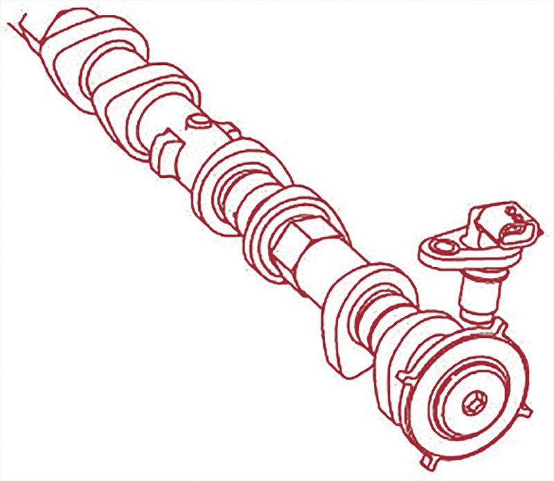 Exhaust Valve Timing Control Position Sensor and its signal plate mounted on the rear of the exhaust camshaft.
2.4. Solenoids in VVT Systems
Solenoids are controlled by the ECM to implement desired changes in valve timing by diverting oil pressure to specific chambers in the camshaft sprockets.
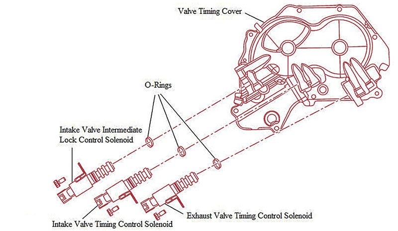 Three valve timing control solenoids mounted in the valve timing cover.
The QR25 engine utilizes three solenoids for valve timing control:
- Intake Valve Timing Control Solenoid
- Exhaust Valve Timing Control Solenoid
- Intake Valve Intermediate Lock Control Solenoid
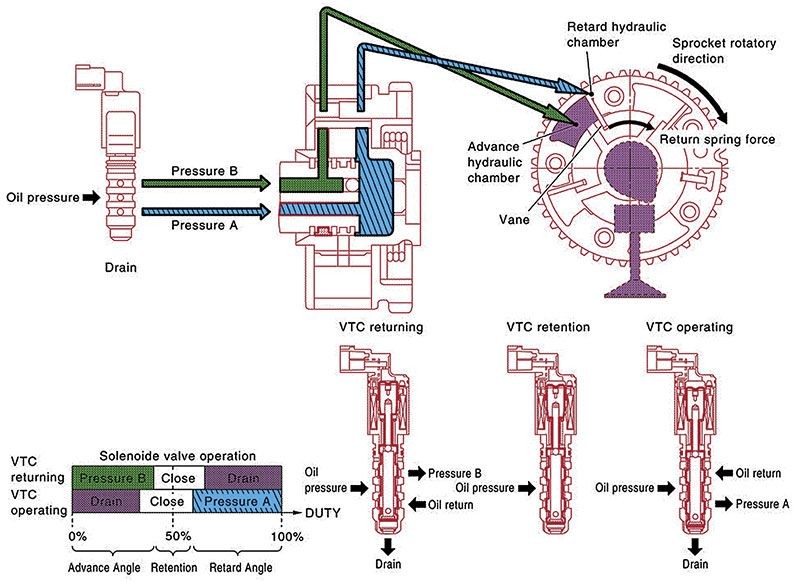 How the exhaust valve timing solenoid works.
3. How DTCs Help Pinpoint VVT Issues
Diagnostic Trouble Codes (DTCs) are essential for diagnosing issues within the VVT system. These codes provide specific information about the nature and location of the problem, streamlining the diagnostic process.
3.1. Common VVT-Related DTCs
Here are some common DTCs associated with the valve timing control system of the QR25 engine:
- P0011: IVT Control (Intake Valve Timing Control)
- P0014: EVT Control (Exhaust Valve Timing Control)
- P0075: Intake Valve Timing Control
- P0078: EVT Control Solenoid Valve
- P0335: CKP Sensor (Crankshaft Position Sensor)
- P0340: CMP Sensor (Camshaft Position Sensor)
- P052A/P052B: Intake Valve Timing Control
- P1078: EVT Control Position Sensor
- P0643: Sensor Power Supply
3.2. Initial Steps in DTC Diagnosis
The first step in diagnosing any DTC is confirmation. This process varies depending on the conditions under which the DTC was set.
- Electrical Faults: Start the engine and let it idle for five seconds.
- Driving Condition Faults: Recreate the conditions in the freeze frame data, ensuring vehicle speed is within 6 mph, engine speed is within 400 rpm, and coolant temperature is within 20°F.
3.3. Addressing Multiple DTCs
When multiple codes are present, identify the primary fault. For instance, if P0011, P0075, and P0300 are set, the primary issue is likely in the intake valve solenoid electrical circuit, leading to an incorrect intake phase angle and a random misfire.
4. Detailed Diagnostic Procedures for Specific DTCs
Understanding how to diagnose specific DTCs related to the VVT system is essential for effective repairs. Here are detailed procedures for some common VVT-related DTCs.
4.1. Diagnosing P0643: Sensor Power Supply
P0643 indicates an issue with the sensor power supply. This code is often accompanied by other codes and should be addressed first.
4.1.1. Understanding the Issue
The PCM sends a 5V reference voltage to multiple sensors, divided into two groups. A short circuit in one circuit affects all sensors on that circuit.
4.1.2. Diagnostic Steps
- Check for voltage and continuity along the circuits.
- Identify any shorts or open circuits in the 5V reference lines.
- Repair any wiring issues and replace any faulty sensors.
4.2. Diagnosing P0075 & P0078: Solenoid Circuit Issues
P0075 indicates an abnormal voltage in the intake valve control solenoid or the intermediate lock solenoid circuit. P0078 indicates an improper voltage from the exhaust valve timing control solenoid.
4.2.1. Diagnostic Steps
- Check Power and Ground: Test each circuit for proper power and ground.
- Solenoid Testing: If the circuit is functional, test the individual solenoids.
- Continuity Check: Check for continuity between specific terminals.
- Resistance Measurement: Measure the resistance of the solenoid coil (typically 7-8 ohms at 68°F).
- Plunger Movement: Apply 12V briefly to the solenoid and interrupt it to observe plunger movement. Ensure it moves freely without binding. Limit power application to 5 seconds to avoid coil damage.
4.3. Diagnosing P0011, P052A, P052B, & P0014: Camshaft Angle Issues
These codes indicate a discrepancy between the target and measured camshaft angles. P0011 is set when the intake camshaft is out of phase at operating temperature, P0014 when the exhaust camshaft is out of phase, P052A when the intake camshaft is over-advanced at cold start, and P052B when the intake camshaft is over-retarded at cold start.
4.3.1. Possible Causes
- Faulty sensors or solenoids
- Clogged oil passages or filters
- Problems with the signal plate
- Stretched or misaligned timing chain
4.3.2. Diagnostic Steps
- Solenoid Check: Follow the P0075 diagnostic procedure to check the solenoids.
- POS and PHASE Sensor Testing:
- Visually inspect the sensors and signal plate for damage.
- Measure resistance across the sensor terminals.
- Timing Chain and Lubrication System Inspection:
- Check static timing by verifying alignment of POS and PHASE signals on an oscilloscope or visually inspecting alignment marks after removing valve covers.
- Remove the timing control solenoids and disable fuel injectors. Crank the engine to observe oil flow at the oil holes in the valve timing control cover.
5. Advanced Diagnostic Techniques
To accurately diagnose VVT issues, advanced techniques and tools may be necessary. These methods can help identify intermittent faults and ensure proper system functionality.
5.1. Using Oscilloscopes for Sensor Analysis
An oscilloscope is invaluable for monitoring the signals from the POS and PHASE sensors. It can detect fluctuations caused by intermittently failing sensors, providing detailed insights into sensor performance.
5.2. Checking Static Timing
Static timing should be checked, especially if there’s a history of timing chain issues or recent repairs. This can be done by:
- Oscilloscope Analysis: Checking the alignment of POS and PHASE signals.
- Visual Inspection: Removing valve covers and verifying alignment marks.
5.3. Lubrication Circuit Inspection
Inspect the lubrication circuit to ensure proper oil flow to the VVT components. This involves:
- Removing the timing control solenoids.
- Disabling the fuel injectors.
- Cranking the engine to observe oil flow at the oil holes.
6. Addressing Intermittent Issues
Intermittent issues can be challenging to diagnose. If no faults are found during the initial diagnostic procedures, consider the following:
6.1. Intermittent Incident Diagnosis
Simulate the conditions present when the fault occurred. This includes:
- Tugging on wires to check for loose connections.
- Disconnecting connectors to inspect for corrosion.
- Heating or cooling specific components.
- Checking components for water intrusion.
- Turning on all electrical loads.
6.2. Real-World Examples
Consider a scenario where a Mercedes-Benz owner experiences intermittent engine performance issues without any consistent DTCs. By using advanced diagnostic tools and techniques, technicians can monitor the VVT system in real-time, identifying subtle variations in valve timing that indicate a developing problem. This proactive approach can prevent more significant issues down the road.
7. Importance of Following Service Manual Procedures
Always adhere to the procedures outlined in the service manual to avoid damaging components or causing injuries. The service manual provides detailed instructions and specifications for each diagnostic and repair procedure, ensuring accuracy and safety.
7.1. Example: Replacing VVT Components
When replacing VVT components, such as solenoids or sensors, follow the manufacturer’s guidelines for installation and calibration. Using the correct torque specifications and alignment procedures is crucial for proper system function and longevity.
8. Benefits of Using MERCEDES-DIAGNOSTIC-TOOL.EDU.VN
At MERCEDES-DIAGNOSTIC-TOOL.EDU.VN, we understand the complexities of diagnosing and repairing modern vehicle systems. Our comprehensive resources and expert support can help you confidently tackle VVT issues.
8.1. Expert Guidance and Support
Our team of experienced technicians provides expert guidance and support, helping you navigate the diagnostic process and identify the root cause of VVT problems. We offer step-by-step instructions, troubleshooting tips, and access to a wealth of technical information.
8.2. Comprehensive Diagnostic Tools
We offer a range of diagnostic tools specifically designed for Mercedes-Benz vehicles. These tools provide detailed insights into the VVT system, allowing you to monitor sensor data, perform component tests, and identify faults quickly and accurately.
8.3. Real-Time Data Monitoring
Our diagnostic tools enable real-time data monitoring, allowing you to observe VVT system performance under various driving conditions. This feature is invaluable for diagnosing intermittent issues and verifying the effectiveness of repairs.
8.4. Addressing Complex Issues
Modern VVT systems are complex, and diagnosing issues can be challenging. Our tools and resources help you:
- Identify Intermittent Faults: Our advanced diagnostic tools can detect subtle variations in VVT system performance, helping you identify intermittent faults before they cause significant problems.
- Verify Repairs: After performing repairs, our tools allow you to verify the effectiveness of your work, ensuring the VVT system is functioning correctly.
- Access Expert Support: Our team of experienced technicians is available to provide expert guidance and support, helping you navigate the diagnostic process and resolve complex VVT issues.
9. Staying Updated with the Latest VVT Technologies
As VVT technology evolves, staying updated with the latest advancements is essential for effective diagnostics and repairs.
9.1. Continuous Learning and Training
MERCEDES-DIAGNOSTIC-TOOL.EDU.VN offers continuous learning and training resources, helping you stay ahead of the curve. Our courses and workshops cover the latest VVT technologies, diagnostic techniques, and repair procedures.
9.2. Access to Updated Information
We provide access to updated technical information, service bulletins, and diagnostic tips, ensuring you have the knowledge and resources needed to tackle even the most challenging VVT issues.
10. Call to Action
Are you struggling with VVT issues on your Mercedes-Benz? Do you need expert guidance and support to diagnose and repair these complex systems? Contact us today at MERCEDES-DIAGNOSTIC-TOOL.EDU.VN for comprehensive diagnostic tools, expert support, and continuous learning resources. Let us help you confidently tackle VVT problems and keep your Mercedes-Benz running smoothly.
For further assistance, visit us at 789 Oak Avenue, Miami, FL 33101, United States, or contact us via WhatsApp at +1 (641) 206-8880. Our website, MERCEDES-DIAGNOSTIC-TOOL.EDU.VN, is your go-to resource for all things Mercedes-Benz diagnostics and repair.
11. FAQs About VVT Systems and DTCs
11.1. What is Variable Valve Timing (VVT)?
Variable Valve Timing (VVT) is a technology used in modern engines to improve performance, fuel efficiency, and reduce emissions by adjusting the timing of the intake and exhaust valves.
11.2. How does VVT improve engine performance?
VVT optimizes valve timing for different engine speeds and loads, maximizing power and torque at high RPM while maintaining drivability at low RPM.
11.3. What are common symptoms of VVT problems?
Common symptoms include reduced engine performance, poor fuel economy, rough idling, and the illumination of the check engine light.
11.4. What is the meaning of DTC P0011?
DTC P0011 indicates an issue with the intake valve timing control system, specifically that the intake camshaft is over-advanced or that the system is not responding as expected.
11.5. What is the meaning of DTC P0014?
DTC P0014 indicates an issue with the exhaust valve timing control system, specifically that the exhaust camshaft is over-advanced or that the system is not responding as expected.
11.6. Can low oil level cause VVT problems?
Yes, low oil level or pressure can cause VVT problems, as the system relies on oil pressure to actuate the valve timing adjustments.
11.7. How do I diagnose VVT problems?
Diagnosing VVT problems involves using a diagnostic scanner to read DTCs, inspecting the VVT components, and testing the sensors and solenoids.
11.8. What tools are needed to diagnose VVT issues?
Essential tools include a diagnostic scanner, multimeter, oscilloscope, and the vehicle’s service manual.
11.9. How often should I inspect my VVT system?
The VVT system should be inspected as part of your vehicle’s regular maintenance schedule, typically every 30,000 to 60,000 miles.
11.10. Can I fix VVT problems myself?
Minor VVT problems, such as replacing a faulty sensor, can be fixed with basic mechanical knowledge. However, more complex issues may require professional assistance.
This comprehensive guide provides valuable insights into how DTCs help pinpoint issues in complex systems like variable valve timing, specifically focusing on codes P0011 and P0014. At MERCEDES-DIAGNOSTIC-TOOL.EDU.VN, we are committed to providing the resources and support you need to diagnose and repair VVT problems efficiently and effectively.