Canbus Obd2 serves as a vital interface for accessing your vehicle’s diagnostic information, enabling efficient troubleshooting and performance monitoring, and at MERCEDES-DIAGNOSTIC-TOOL.EDU.VN, we ensure you understand and utilize this technology effectively. With our expert guidance, you can seamlessly retrieve diagnostic trouble codes (DTCs) and real-time data, enhancing your vehicle’s maintenance and performance. Delve into enhanced vehicle diagnostics, standardized protocols, and efficient troubleshooting using our resources.
Contents
- 1. Understanding OBD2 and Its Significance
- 1.1. What is OBD2?
- 1.2. Why is OBD2 Important?
- 1.3. The Malfunction Indicator Light (MIL)
- 2. Compatibility: Does Your Car Support OBD2?
- 2.1. OBD2 Support in Modern Cars
- 2.2. Historical Context of OBD2 Implementation
- 2.3. Identifying OBD2 Compliance
- 3. Evolution of OBD2: History and Future Trends
- 3.1. OBD2’s Origin in California
- 3.2. Key Milestones in OBD2 Development
- 3.3. Future Trends: OBD3 and Beyond
- 4. Alternatives to Traditional OBD2
- 4.1. Electric Vehicles and OBD2
- 4.2. OBD2 and Third-Party Data Access
- 4.3. The Debate Over Data Control
- 5. Key OBD2 Standards: SAE J1962 and More
- 5.1. The OSI Model and OBD2 Standards
- 5.2. SAE J1962: The OBD2 Connector
- 5.3. Key Features of the OBD2 Connector
- 6. Decoding the OBD2 Connector: Type A vs. B
- 6.1. Type A OBD2 Connector
- 6.2. Type B OBD2 Connector
- 6.3. Distinguishing Between Type A and Type B
- 7. Integrating OBD2 and CAN Bus: The ISO 15765-4 Standard
- 7.1. What is ISO 15765-4?
- 7.2. Key Aspects of ISO 15765-4
- 7.3. Understanding CAN Identifiers
- 8. OBD2 vs. Proprietary CAN Protocols
- 8.1. Understanding OEM-Specific CAN Protocols
- 8.2. OBD2 as an Additional Protocol
- 8.3. Bit-Rate and ID Validation
- 9. Exploring Lower-Layer OBD2 Protocols
- 9.1. CAN Bus (ISO 15765)
- 9.2. Keyword Protocol 2000 (ISO14230-4)
- 9.3. ISO 9141-2
- 9.4. SAE J1850 (VPW and PWM)
- 10. Transporting OBD2 Messages via ISO-TP (ISO 15765-2)
- 11. The OBD2 Diagnostic Message: SAE J1979, ISO 15031-5
- 11.1. Dissecting an OBD2 Message
- 11.2. Request/Response Example
- 11.3. Exploring OBD2 Modes (Services)
- 12. Understanding OBD2 Parameter IDs (PIDs)
- 12.1. Standardized PIDs in Mode 0x01
- 12.2. The Significance of PID 0x00
- 12.3. Leveraging an OBD2 PID Overview Tool
- 13. Practical Guide: Logging and Decoding OBD2 Data
- 13.1. Testing Bit-Rate, IDs, and Supported PIDs
1. Understanding OBD2 and Its Significance
OBD2 (On-Board Diagnostics II) is your vehicle’s self-diagnostic system, offering standardized access to vital data for maintenance and troubleshooting. It is a standardized protocol that allows extraction of diagnostic trouble codes (DTCs) and real-time data via the OBD2 connector. This system is crucial for monitoring vehicle health and identifying potential issues early.
1.1. What is OBD2?
OBD2 is the standardized system that allows you to tap into your car’s computer. It provides access to a wealth of information about your vehicle’s performance and health. Think of it as your car’s built-in check-up tool.
1.2. Why is OBD2 Important?
OBD2 is important because it empowers vehicle owners and technicians to quickly diagnose problems. By accessing DTCs and real-time data, you can address issues before they escalate, potentially saving money on costly repairs. This is particularly valuable for owners of Mercedes-Benz vehicles, who often seek precise and reliable diagnostic information.
1.3. The Malfunction Indicator Light (MIL)
The malfunction indicator light, often called the check engine light, is a key indicator of potential problems detected by the OBD2 system. When this light illuminates, it signals that the vehicle’s computer has detected an issue that needs attention.
2. Compatibility: Does Your Car Support OBD2?
Chances are, if you own a newer car, it supports OBD2. The standardization of OBD2 has made it a ubiquitous feature in modern vehicles.
2.1. OBD2 Support in Modern Cars
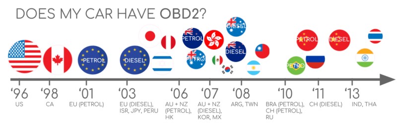
Almost all non-electric cars support OBD2 and most run on CAN bus. For older cars, note that even if a 16 pin OBD2 connector is present, it may still not support OBD2. One way to determine compliance is to see where & when it was bought new:
2.2. Historical Context of OBD2 Implementation
OBD2’s implementation was rolled out gradually. In 1996, it became mandatory in the USA for cars and light trucks. By 2001, it was required in the EU for gasoline cars, and in 2003 for diesel cars (EOBD). By 2008, US cars were mandated to use ISO 15765-4 (CAN) as the basis for OBD2.
 Does My Car Have OBD2?
2.3. Identifying OBD2 Compliance
One way to determine compliance is to see where & when it was bought new. Even if a 16-pin OBD2 connector is present, it may still not support OBD2. For Mercedes-Benz owners, checking the vehicle’s documentation or contacting a certified technician can confirm OBD2 compatibility.
3. Evolution of OBD2: History and Future Trends
OBD2 has evolved significantly since its inception. Understanding its history and future trends can help you appreciate its role in modern vehicle diagnostics.
3.1. OBD2’s Origin in California
OBD2 originates from California where the California Air Resources Board (CARB) required OBD in all new cars from 1991+ for emission control purposes.
The OBD2 standard was recommended by the Society of Automotive Engineers (SAE) and standardized DTCs and the OBD connector across manufacturers (SAE J1962).
3.2. Key Milestones in OBD2 Development
From there, the OBD2 standard was rolled out step-by-step:
- 1996: OBD2 made mandatory in USA for cars/light trucks
- 2001: Required in EU for gasoline cars
- 2003: Required in EU also for diesel cars (EOBD)
- 2005: OBD2 was required in US for medium duty vehicles
- 2008: US cars must use ISO 15765-4 (CAN) as OBD2 basis
- 2010: Finally, OBD2 was required in US heavy duty vehicles
3.3. Future Trends: OBD3 and Beyond
OBD2 is here to stay – but in what form?
Legislated OBD2 has originally been designed for the purpose of emissions control/testing. As an implication, electric vehicles are not required to support OBD2 in any shape or form. This can be seen in practice from the fact that almost none of the modern EVs support any of the standard OBD2 requests. Instead, most of them utilize OEM-specific UDS communication.
Looking ahead, OBD3 aims to add telematics to all cars, enabling remote diagnostics and emissions testing. While this offers convenience, it also raises concerns about surveillance and data privacy.
4. Alternatives to Traditional OBD2
OBD2 is today implemented in a variety of ways and has limitations in regards to e.g. data richness and lower-layer protocols. In response to this, modern alternatives have been developed including WWH-OBD (World Wide Harmonized OBD) and OBDonUDS (OBD on UDS). Both seek to streamline and enhance OBD communication by leveraging the UDS protocol as basis. To learn more about these protocols, see our intro to UDS.
4.1. Electric Vehicles and OBD2
As an implication, electric vehicles are not required to support OBD2 in any shape or form. This can be seen in practice from the fact that almost none of the modern EVs support any of the standard OBD2 requests. Instead, most of them utilize OEM-specific UDS communication. Generally, this makes it impossible to decode data from these electric vehicles, except for cases where the decoding rules have been reverse engineered – see e.g. our case studies for electric cars incl. Tesla, Hyundai/Kia, Nissan and VW/Skoda EVs.
4.2. OBD2 and Third-Party Data Access
In today’s world of connected cars, OBD2 tests can seem cumbersome: Manually doing emission control checks is time-consuming and expensive. The solution? OBD3 – adding telematics to all cars.
Basically, OBD3 adds a small radio transponder (as in e.g. bridge tolls) to all cars. Using this, the car vehicle identification number (VIN) and DTCs can be sent via WiFi to a central server for checks.
Many devices today already facilitate transfer of CAN or OBD2 data via WiFi/cellular – e.g. the CANedge2 WiFi CAN logger or the CANedge3 3G/4G CAN logger.
This saves cost and is convenient, but it is also politically a challenge due to surveillance concerns. The OBD2 protocol was originally designed for stationary emission controls.
4.3. The Debate Over Data Control
Yet, today OBD2 is used extensively for generating real-time data by 3rd parties – via OBD2 dongles, CAN loggers etc. However, the German car industry is looking to change this:
OBD has been designed to service cars in repair shops. In no way has it been intended to allow third parties to build a form of data-driven economy on the access through this interface“
– Christoph Grote, SVP Electronics, BMW (2017)
The proposal is to “turn off” the OBD2 functionality while driving – and instead collect the data in a central server. This would effectively put the manufacturers in control of the ‘automotive big data’.
The argumentation is based in security (e.g. removing the risk of car hacking), though many see it as a commercial move. Whether this becomes a real trend is to be seen – but it may truly disrupt the market for OBD2 3rd party services.
5. Key OBD2 Standards: SAE J1962 and More
On board diagnostics, OBD2, is a higher layer protocol (like a language). CAN is a method for communication (like a phone). This makes OBD2 comparable to other CAN based higher-layer protocols like J1939, CANopen and NMEA 2000.
In particular, the OBD2 standards specify the OBD2 connector, lower-layer protocols, OBD2 parameter IDs (PID) and more.
The standards can be displayed in a 7-layer OSI model – and in the next sections we focus on the most important ones.
In the OSI model overview, you may note that several layers are covered by both SAE and ISO standards. Generally, this reflects standards for OBD defined in USA (SAE) and EU (ISO). Several standards are almost technically equivalent, for example SAE J1979 vs. ISO 15031-5 and SAE J1962 vs. ISO 15031-3.
5.1. The OSI Model and OBD2 Standards
The OBD2 standards are often displayed in a 7-layer OSI model. Several layers are covered by both SAE and ISO standards, reflecting standards for OBD defined in the USA (SAE) and EU (ISO).
5.2. SAE J1962: The OBD2 Connector
The 16-pin OBD2 connector is standardized in SAE J1962 / ISO 15031-3. This connector provides easy access to your car’s data.
5.3. Key Features of the OBD2 Connector
A few things to note:
- The connector is near your steering wheel, but may be hidden
- Pin 16 supplies battery power (often while the ignition is off)
- The OBD2 pinout depends on the communication protocol
- The most common lower-layer protocol is CAN bus, meaning that pins 6 (CAN-H) and 14 (CAN-L) will typically be connected
[
](https://www.csselectronics.com/cdn/shop/files/obd2-connector-pinout-socket.svg?v=1633690039)
6. Decoding the OBD2 Connector: Type A vs. B
The OBD2 connector comes in two types, A and B. Understanding the differences can help you select the right adapter and ensure compatibility.
6.1. Type A OBD2 Connector
Typically, type A will be found in cars.
6.2. Type B OBD2 Connector
Type B is common in medium and heavy duty vehicles.
6.3. Distinguishing Between Type A and Type B
As evident from the illustration, the two types share similar OBD2 pinouts, but provide two different power supply outputs (12V for type A and 24V for type B). Often the baud rate will differ as well, with cars typically using 500K, while most heavy duty vehicles use 250K (more recently with support for 500K).
To help physically distinguish between the two types of OBD2 sockets, note that the type B OBD2 connector has an interrupted groove in the middle. As a result, a type B OBD2 adapter cable will be compatible with both types A and B, while a type A will not fit into a type B socket.
7. Integrating OBD2 and CAN Bus: The ISO 15765-4 Standard
Since 2008, CAN bus has been the mandatory lower-layer protocol for OBD2 in all cars sold in the US as per ISO 15765. The CAN (Controller Area Network) bus is the backbone of modern vehicle communication.
7.1. What is ISO 15765-4?
ISO 15765-4 (aka Diagnostics over CAN or DoCAN) refers to a set of restrictions applied to the CAN standard (ISO 11898). Specifically, it standardizes the CAN interface for test equipment with focus on the physical, data link and network layer:
- The CAN bus bit-rate must be either 250K or 500K
- The CAN IDs can be 11-bit or 29-bit
- Specific CAN IDs are used for OBD requests/responses
- The diagnostic CAN frame data length must be 8 bytes
- The OBD2 adapter cable must be max 5 meters
7.2. Key Aspects of ISO 15765-4
Key aspects of ISO 15765-4 include the CAN bus bit-rate (250K or 500K), CAN ID lengths (11-bit or 29-bit), specific CAN IDs for OBD requests/responses, diagnostic CAN frame data length (8 bytes), and the maximum length of the OBD2 adapter cable (5 meters).
7.3. Understanding CAN Identifiers
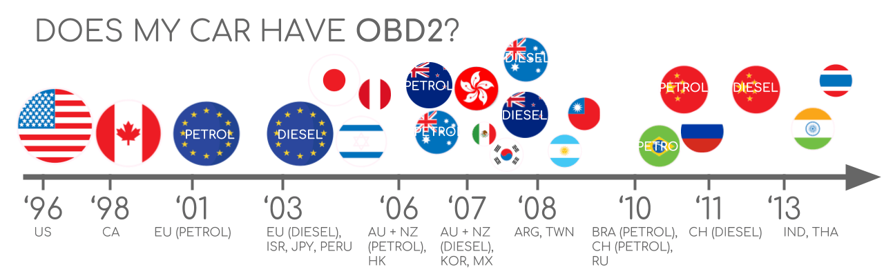
All OBD2 communication involves request / response messages.
In most cars, 11-bit CAN IDs are used for OBD2 communication. Here, the ‘Functional Addressing’ ID is 0x7DF, which corresponds to asking all OBD2 compatible ECUs if they have data to report on the requested parameter (see ISO 15765-4). In contrast, CAN IDs 0x7E0-0x7E7 can be used to perform ‘Physical Addressing’ requests from specific ECUs (less commonly used).
ECUs can respond with 11-bit IDs 0x7E8-0x7EF. The most common response ID is 0x7E8 (ECM, Engine Control Module) and to some extent 0x7E9 (TCM, Transmission Control Module).
In some vehicles (e.g. vans and light/medium/heavy duty vehicles), you may find that OBD2 communication uses extended 29-bit CAN identifiers instead of 11-bit CAN identifiers.
Here, the ‘Functional Addressing’ CAN ID is 0x18DB33F1.
If the vehicle responds, you will see responses with CAN IDs 0x18DAF100 to 0x18DAF1FF (typically 18DAF110 and 18DAF11E). The response ID is also sometimes shown in the ‘J1939 PGN’ form, specifically the PGN 0xDA00 (55808), which in the J1939-71 standard is marked as ‘Reserved for ISO 15765-2’.
 OBD2 OBD CAN bus Identifiers 7DF 7E8 7E0
8. OBD2 vs. Proprietary CAN Protocols
Importantly, your car’s electronic control units (ECUs) do not rely on OBD2 to function. Rather, each original equipment manufacturer (OEM) implements their own proprietary CAN protocols for this purpose. These CAN protocols may be specific to the vehicle brand, model and year. If you are not the OEM, you will normally not be able to interpret this data (unless you can reverse engineer it).
If you connect a CAN bus data logger to your car’s OBD2 connector, you may see the OEM-specific CAN data, typically broadcast at a rate of 1000-2000 frames/second. However, in many newer cars a ‘gateway’ blocks access to this CAN data and only enables OBD2 communication via the OBD2 connector.
In short, think of OBD2 as an ‘extra’ higher-layer protocol in parallel to the OEM-specific protocol.
8.1. Understanding OEM-Specific CAN Protocols
OEMs implement their own CAN protocols for ECU communication. These protocols are often specific to the vehicle brand, model, and year.
8.2. OBD2 as an Additional Protocol
Think of OBD2 as an ‘extra’ higher-layer protocol in parallel to the OEM-specific protocol. OBD2 is an additional layer that provides standardized access to certain vehicle data, while the OEM-specific protocols handle the core functionality of the ECUs.
8.3. Bit-Rate and ID Validation
As explained, OBD2 may use one of two bit-rates (250K, 500K) and one of two CAN ID lengths (11-bit, 29-bit). This results in 4 potential combinations. In modern cars, 500K and 11-bit IDs is the most common one – but external tools should verify this in a systematic way.
ISO 15765-4 provides recommendations for how to perform a systematic initialization sequence to determine the relevant combination, which we illustrate in the flowchart. The method leverages that OBD2 compliant vehicles must respond to a specific mandatory OBD2 request (see the OBD2 PID section for details) – and the fact that transmitting data with an incorrect bit-rate will cause CAN error frames.
Newer versions of ISO 15765-4 take into account that vehicles may support OBD communication via OBDonUDS rather than OBDonEDS. Most of this article focuses on OBD2/OBDonEDS (OBD on emission diagnostic service as per ISO 15031-5/SAE J1979) as opposed to WWH-OBD/OBDonUDS (OBD on Unified Diagnostic Service as per ISO 14229, ISO 27145-3/SAE J1979-2).
To test for the ‘protocol’ of OBDonEDS vs OBDonUDS, a test tool may add additional request messages, specifically sending UDS requests with 11-bit/29-bit functional address IDs for service 0x22 and data identifier (DID) 0xF810 (protocol identification). Vehicles that support OBDonUDS must have ECUs that reply to this DID.
In practice, OBDonEDS (aka OBD2, SAE OBD, EOBD or ISO OBD) is used in most non-EV cars today, while WWH-OBD is primarily used in EU trucks/buses.
9. Exploring Lower-Layer OBD2 Protocols
CAN today serves as the lower-layer basis for OBD2 in the vast majority of cars as per ISO 15765.
However, if you inspect an older car (pre 2008), it is useful to know the other four lower-layer protocols that have been used as basis for OBD2. Note also the pinouts, which can be used to determine which protocol may be used in your car.
- ISO 15765 (CAN bus): Mandatory in US cars since 2008 and is today used in the vast majority of cars
- ISO14230-4 (KWP2000): The Keyword Protocol 2000 was a common protocol for 2003+ cars in e.g. Asia
- ISO 9141-2: Used in EU, Chrysler & Asian cars in 2000-04
- SAE J1850 (VPW): Used mostly in older GM cars
- SAE J1850 (PWM): Used mostly in older Ford cars
9.1. CAN Bus (ISO 15765)
Mandatory in US cars since 2008 and is today used in the vast majority of cars.
9.2. Keyword Protocol 2000 (ISO14230-4)
The Keyword Protocol 2000 was a common protocol for 2003+ cars in e.g. Asia.
9.3. ISO 9141-2
Used in EU, Chrysler & Asian cars in 2000-04.
9.4. SAE J1850 (VPW and PWM)
Used mostly in older GM and Ford cars.
10. Transporting OBD2 Messages via ISO-TP (ISO 15765-2)
All OBD2 data is communicated on the CAN bus through a transport protocol called ISO-TP (ISO 15765-2). This enables communication of payloads that exceed 8 bytes. This is necessary in OBD2 e.g. when extracting the Vehicle Identification Number (VIN) or Diagnostic Trouble Codes (DTCs). Here, ISO 15765-2 enables segmentation, flow control and reassembly. For details, see our intro to UDS.
Often, however, the OBD2 data will fit in a single CAN frame. Here, ISO 15765-2 specifies the use of a ‘Single Frame’ (SF), implying that the 1st data byte (aka PCI field) contains the payload length (excluding padding), leaving 7 bytes for the OBD2 related communication.
11. The OBD2 Diagnostic Message: SAE J1979, ISO 15031-5
To better understand OBD2 on CAN, let us consider a raw ‘Single Frame’ OBD2 CAN message. In simplified terms, an OBD2 message is comprised of an identifier, data length (PCI field) and data. The data is split in Mode, parameter ID (PID) and data bytes.
11.1. Dissecting an OBD2 Message
In simplified terms, an OBD2 message is comprised of an identifier, data length (PCI field) and data. The data is split into Mode, parameter ID (PID), and data bytes.
11.2. Request/Response Example
Before we cover each part of the OBD2 message, consider this example request/response for the parameter ‘Vehicle Speed’.
Here, an external tool sends a request message to the car with CAN ID 0x7DF and 2 payload bytes: Mode 0x01 and PID 0x0D. The car responds via CAN ID 0x7E8 and 3 payload bytes, including the value of Vehicle Speed in the 4th byte, 0x32 (50 in decimal form).
By looking up the decoding rules for OBD2 PID 0x0D we determine that the physical value is 50 km/h.
Next, we will focus on the OBD2 modes and PIDs.
11.3. Exploring OBD2 Modes (Services)
There are 10 OBD2 diagnostic services (or modes). Mode 0x01 shows current real-time data, while others are used to show/clear diagnostic trouble codes (DTCs) or show freeze frame data.
Vehicles do not have to support all OBD2 modes – and they may support modes outside the 10 standardized modes (aka OEM-specific OBD2 modes).
In OBD2 messages, the mode is in the 2nd byte. In the request, the mode is included directly (e.g. 0x01), while in the response 0x40 is added to the mode (e.g. resulting in 0x41).
12. Understanding OBD2 Parameter IDs (PIDs)
Each OBD2 mode contains parameter IDs (PIDs).
12.1. Standardized PIDs in Mode 0x01
As an example, mode 0x01 contains ~200 standardized PIDs with real-time data on e.g. speed, RPM and fuel level. However, a vehicle does not have to support all OBD2 PIDs in a mode. In practice, most vehicles only support a small subset.
12.2. The Significance of PID 0x00
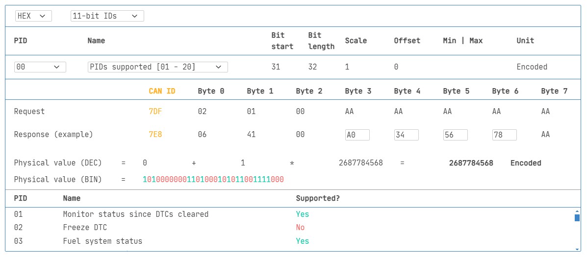
In this regard, one PID is special.
Specifically, if an emissions-related ECU supports any OBD2 services, then it must support mode 0x01 PID 0x00. In response to this PID, the vehicle ECU informs whether it supports PIDs 0x01-0x20. This makes PID 0x00 useful as a fundamental ‘OBD2 compatibility test’. Further, PIDs 0x20, 0x40, …, 0xC0 can be used to determine the support for the remaining mode 0x01 PIDs.
 OBD2 PID overview tool
12.3. Leveraging an OBD2 PID Overview Tool
In the appendices of SAE J1979 and ISO 15031-5 you will find scaling info for standard OBD2 PIDs, which allows you to decode the data into physical values (as explained in our CAN bus intro).
If you need to look up a mode 0x01 PID, check out our OBD2 PID overview tool. This helps you construct OBD2 request frames and dynamically decode the OBD2 responses.
OBD2 PID overview tool
13. Practical Guide: Logging and Decoding OBD2 Data
In this section we provide a practical example of how you can log OBD2 data with the CANedge CAN bus data logger.
The CANedge lets you configure custom CAN frames to be transmitted which allows it to be used for e.g. OBD2 logging.
Once configured, the device can be easily connected to your vehicle via our OBD2-DB9 adapter cable.
13.1. Testing Bit-Rate, IDs, and Supported PIDs
As discussed, ISO 15765-4 describes how to determine which bit-rate and IDs are used by a specific vehicle. You can test this with the CANedge as below (see the CANedge Intro for details):
- Send CAN frame at 500K and check if succesful (else try 250K)
- Use the identified bit-rate for subsequent communication
- Send multiple ‘Supported PIDs’ requests and review the results
- Based on response IDs you can determine 11-bit vs. 29-bit
- Based on response data you can see what PIDs are supported
We provide plug & play configs to perform the above tests.
Most 2008+ non-EV cars support 40-80 PIDs via 500K bit-rate, 11-bit CAN IDs and the OBD2/OBDonEDS protocol.
As exemplified in the asammdf GUI screenshot, it is common to see multiple responses to a single OBD request. This is because we use the 0x7DF request ID, which polls all ECUs for a response. Since all OBD2/OBDonEDS-compliant ECUs must support service 0x01 PID 0x00, there are often many responses to this PID in particular. As evident, for subsequent ‘Supported PIDs’ requests there are gradually fewer ECUs that respond. Note also that the ECM ECU (0x7E8) itself supports all the PIDs that are supported by other ECUs in this example,