OBD2 to USB wiring diagram is crucial for Mercedes-Benz owners looking to perform diagnostics and customization. This guide from MERCEDES-DIAGNOSTIC-TOOL.EDU.VN provides a comprehensive, step-by-step approach to creating your own OBD2 to USB interface, enabling you to access advanced vehicle data and functionality. Unlock the potential of your Mercedes-Benz with our expert guidance on automotive diagnostics and DIY car repairs, enhancing your vehicle’s performance and personalization.
Contents
- 1. Understanding the Basics of OBD2 to USB Wiring
- 1.1. What is OBD2 and How Does It Work?
- 1.2. Why Use USB for OBD2 Connections?
- 1.3. Key Components of an OBD2 to USB Wiring Diagram
- 2. Identifying User Search Intent
- 2.1. Saving Money on Diagnostic Tools
- 2.2. Accessing Advanced Vehicle Data
- 2.3. Learning About Automotive Technology
- 2.4. Troubleshooting Existing Adapters
- 2.5. Adapting Tools for Specific Purposes
- 3. Essential Tools and Components
- 3.1. Wire Strippers/Cutters
- 3.2. Needle-Nose Pliers
- 3.3. Soldering Iron (Recommended)
- 3.4. Multimeter
- 3.5. OBD2 Connector
- 3.6. USB Connector
- 3.7. Wires
- 4. Step-by-Step Guide to Creating Your OBD2 to USB Wiring
- 4.1. Gathering Your Materials
- 4.2. Preparing the Wires
- 4.3. Connecting Wires to the OBD2 Connector
- 4.4. Connecting Wires to the USB Connector
- 4.5. Testing the Connections
- 5. Understanding Wire Pairing and Twisting
- 5.1. Reducing Electromagnetic Interference (EMI)
- 5.2. Enhancing Signal Integrity
- 5.3. CAN Bus Communication
- 6. Connecting the Wires to the 4-Pin Connector
- 6.1. Wire Sizing and Preparation
- 6.2. Crimping or Soldering
- 6.3. Inserting Pins into the Connector
- 6.4. Ensuring Secure Connections
- 7. Testing Your DIY OBD2 to USB Connector
- 7.1. Continuity Testing with a Multimeter
- 7.2. Connecting to a Vehicle and Computer
- 7.3. Verifying Data Transmission
- 7.4. Using Diagnostic Software
- 8. Safety Precautions
- 8.1. Disconnecting the Vehicle’s Battery
- 8.2. Proper Grounding Techniques
- 8.3. Avoiding Wiring Errors
- 8.4. Using Protective Gear
- 9. Troubleshooting Common Issues
- 9.1. Connectivity Problems
- 9.2. Data Transmission Errors
- 9.3. Software Compatibility Issues
- 9.4. Power Supply Problems
- 10. Benefits of DIY OBD2 to USB Wiring for Mercedes-Benz
- 10.1. Cost Savings
- 10.2. Customized Diagnostics
- 10.3. Access to Advanced Features
- 10.4. Enhanced Learning
- 10.5. Community Support
- 11. Advanced Diagnostic and Customization Options
- 11.1. ECU Programming
- 11.2. Real-Time Data Logging
- 11.3. Custom Parameter Adjustments
- 11.4. Access to Hidden Features
- 12. Cost Savings and DIY Advantages
- 12.1. Comparing Costs
- 12.2. Control and Customization
- 12.3. Learning Opportunities
- 12.4. Convenience
- 13. Expert Tips and Recommendations
- 13.1. Use High-Quality Components
- 13.2. Follow Wiring Diagrams Carefully
- 13.3. Solder Connections for Reliability
- 13.4. Test Each Connection Thoroughly
- 13.5. Consult Online Communities for Support
- 14. Staying Updated with the Latest Mercedes-Benz Technology
- 14.1. Subscribing to Industry Newsletters
- 14.2. Participating in Online Forums
- 14.3. Attending Workshops and Training Sessions
- 14.4. Regularly Visiting MERCEDES-DIAGNOSTIC-TOOL.EDU.VN
- 15. Frequently Asked Questions (FAQ)
- 16. Call to Action
Table of Contents
- Understanding the Basics of OBD2 to USB Wiring
- Identifying User Search Intent
- Essential Tools and Components
- Step-by-Step Guide to Creating Your OBD2 to USB Wiring
- Understanding Wire Pairing and Twisting
- Connecting the Wires to the 4-Pin Connector
- Testing Your DIY OBD2 to USB Connector
- Safety Precautions
- Troubleshooting Common Issues
- Benefits of DIY OBD2 to USB Wiring for Mercedes-Benz
- Advanced Diagnostic and Customization Options
- Cost Savings and DIY Advantages
- Expert Tips and Recommendations
- Staying Updated with the Latest Mercedes-Benz Technology
- Frequently Asked Questions (FAQ)
- Call to Action
1. Understanding the Basics of OBD2 to USB Wiring
What is the significance of understanding OBD2 to USB wiring for Mercedes-Benz owners?
Understanding OBD2 to USB wiring is essential for Mercedes-Benz owners who want to perform their own vehicle diagnostics, customization, and maintenance. An OBD2 (On-Board Diagnostics II) port is a standardized interface found in most modern vehicles, including Mercedes-Benz models, that provides access to the car’s computer system. By creating or purchasing an OBD2 to USB adapter, owners can connect their vehicle to a computer and use specialized software to read diagnostic codes, monitor performance data, and even modify certain vehicle settings. This knowledge empowers owners to take control of their vehicle’s health and performance, potentially saving money on costly dealership visits and enabling personalized enhancements.
1.1. What is OBD2 and How Does It Work?
OBD2, or On-Board Diagnostics II, is a standardized system used in vehicles to monitor and report on various aspects of the vehicle’s performance and health. According to the Environmental Protection Agency (EPA), OBD2 was mandated in the United States for all cars and light trucks manufactured after 1996 to ensure emissions compliance. The OBD2 system uses a standardized 16-pin connector, typically located under the dashboard, to allow access to the vehicle’s computer. When a problem is detected, the system generates diagnostic trouble codes (DTCs) that can be read using a scan tool or OBD2 software.
1.2. Why Use USB for OBD2 Connections?
Using USB for OBD2 connections provides a convenient and universal interface for connecting to computers and other devices. USB (Universal Serial Bus) is a widely adopted standard for data communication and power supply, making it easy to interface with a variety of devices. By converting the OBD2 signal to USB, users can leverage the processing power and display capabilities of their computers to perform advanced diagnostics, data logging, and customization. Additionally, many OBD2 software applications are designed to work with USB interfaces, providing a user-friendly experience.
1.3. Key Components of an OBD2 to USB Wiring Diagram
The key components of an OBD2 to USB wiring diagram include the OBD2 connector, the USB connector, and the necessary wiring to connect the appropriate pins between the two. The OBD2 connector has 16 pins, but typically only a few are needed for basic diagnostics:
- Pin 4: Chassis Ground
- Pin 5: Signal Ground
- Pin 6: CAN High (Controller Area Network)
- Pin 14: CAN Low
- Pin 16: Battery Power
The USB connector has four pins:
- Pin 1: VCC (Power)
- Pin 2: Data –
- Pin 3: Data +
- Pin 4: Ground
The wiring diagram specifies which OBD2 pins need to be connected to which USB pins to establish proper communication. Additional components, such as resistors or transceivers, may be required depending on the specific application and the level of functionality desired.
2. Identifying User Search Intent
What are the main reasons users search for “Diy Obd2 To Usb Wiring Diagram” information?
Users search for “DIY OBD2 to USB wiring diagram” information for several key reasons: to save money by creating their own diagnostic tools, to gain deeper access to their vehicle’s data for advanced diagnostics and customization, to learn about automotive technology and electronics, to troubleshoot existing OBD2 to USB adapters, and to adapt or modify existing tools for specific purposes. Understanding these intents helps tailor content to meet their needs effectively.
2.1. Saving Money on Diagnostic Tools
One of the primary reasons users search for DIY OBD2 to USB wiring diagrams is to save money on expensive commercial diagnostic tools. Professional-grade scan tools can cost hundreds or even thousands of dollars, which may be prohibitive for the average car owner or hobbyist. By creating their own OBD2 to USB adapter, users can access many of the same diagnostic capabilities at a fraction of the cost. According to a survey by the Auto Care Association, the average cost of vehicle repair has been steadily increasing, making DIY solutions more attractive.
2.2. Accessing Advanced Vehicle Data
DIY OBD2 to USB wiring allows users to access deeper levels of vehicle data and customization options that may not be available with standard diagnostic tools. By connecting directly to the vehicle’s computer system, users can monitor parameters such as engine performance, sensor readings, and diagnostic trouble codes in real-time. This level of access enables advanced troubleshooting, performance tuning, and customization of vehicle settings. Automotive forums and online communities are filled with examples of enthusiasts using DIY OBD2 adapters to unlock hidden features and optimize their vehicle’s performance.
2.3. Learning About Automotive Technology
For many users, creating their own OBD2 to USB adapter is a way to learn about automotive technology and electronics. Building the adapter requires an understanding of basic wiring, soldering, and electronic components. This hands-on experience can be educational and rewarding, providing users with a deeper understanding of how their vehicle’s systems work. Online resources, such as electronics tutorials and automotive repair guides, provide valuable information and support for those interested in learning about these topics.
2.4. Troubleshooting Existing Adapters
Some users may search for OBD2 to USB wiring diagrams to troubleshoot or repair existing adapters that are not functioning correctly. Over time, the wiring or components in an adapter may become damaged or fail, leading to communication issues. By referencing a wiring diagram, users can identify and repair any broken connections or faulty components, restoring the adapter to proper working condition. Online forums and support communities often provide troubleshooting tips and advice for common adapter issues.
2.5. Adapting Tools for Specific Purposes
Experienced users may want to adapt or modify existing OBD2 to USB adapters for specific purposes, such as data logging, custom programming, or interfacing with specific software applications. A wiring diagram provides the necessary information to understand the adapter’s internal connections and make any necessary modifications. This level of customization allows users to tailor the adapter to their specific needs and create unique solutions for vehicle diagnostics and performance tuning.
3. Essential Tools and Components
What tools and components are necessary to create a DIY OBD2 to USB wiring setup?
Creating a DIY OBD2 to USB wiring setup requires several essential tools and components, including wire strippers/cutters, needle-nose pliers, a soldering iron (recommended), a multimeter, an OBD2 connector, a USB connector, and appropriately sized wires. Having the right tools ensures a safe and effective wiring process, while quality components guarantee reliable communication between your vehicle and computer.
3.1. Wire Strippers/Cutters
Wire strippers and cutters are essential tools for preparing the wires for connection. These tools allow you to remove the insulation from the wires without damaging the conductors, ensuring a clean and reliable connection. Adjustable wire strippers are recommended, as they can accommodate different wire gauges. According to electrical safety standards, using the correct wire stripping technique is crucial for preventing short circuits and ensuring proper electrical conductivity.
3.2. Needle-Nose Pliers
Needle-nose pliers are useful for gripping and manipulating small components, such as the pins on the OBD2 and USB connectors. They can also be used to bend and shape the wires for easier insertion into the connectors. The fine tips of the pliers provide precision and control, making them ideal for working in tight spaces. Proper handling of pliers is important to avoid damaging the components or injuring yourself.
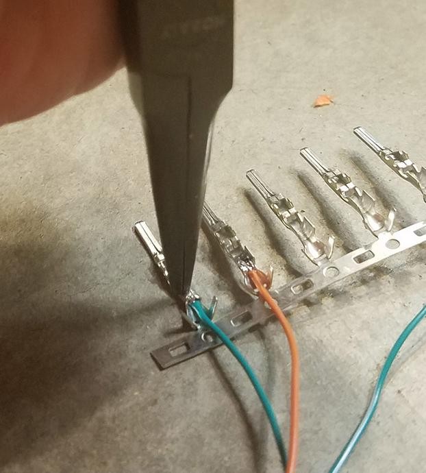
 Needle-nose pliers
Alt text: Close-up of needle-nose pliers holding a small wire connector during the DIY OBD2 to USB wiring process, emphasizing precision.
3.3. Soldering Iron (Recommended)
A soldering iron is highly recommended for creating strong and reliable connections between the wires and the connector pins. Soldering involves melting solder, a metal alloy, to create a permanent bond between the components. This method provides superior electrical conductivity and mechanical strength compared to crimping or twisting the wires together. Proper soldering technique is essential for creating durable and long-lasting connections.
3.4. Multimeter
A multimeter is a versatile tool used to measure voltage, current, and resistance in electrical circuits. It is essential for testing the continuity of the wiring and verifying that the connections are correct. A multimeter can also be used to identify any short circuits or open circuits in the wiring. According to electrical testing guidelines, a multimeter should be used to verify the integrity of all connections before applying power to the circuit.
3.5. OBD2 Connector
The OBD2 connector is a standardized 16-pin connector that plugs into the vehicle’s OBD2 port. These connectors can be purchased from various online retailers or electronic supply stores. When selecting an OBD2 connector, it is important to ensure that it is compatible with the wiring gauge you will be using. High-quality connectors with gold-plated pins are recommended for optimal conductivity and corrosion resistance.
3.6. USB Connector
The USB connector is used to connect the OBD2 adapter to a computer or other USB-enabled device. Standard USB connectors are readily available in various form factors, such as USB-A, USB-B, and USB-C. The choice of USB connector will depend on the type of port available on your computer or device. It is important to ensure that the USB connector is properly shielded to prevent electromagnetic interference.
3.7. Wires
Appropriately sized wires are needed to connect the OBD2 and USB connectors. The wire gauge should be chosen based on the current carrying capacity required for the application. For most OBD2 to USB adapters, 22-26 AWG (American Wire Gauge) wires are sufficient. It is important to use insulated wires to prevent short circuits and ensure electrical safety. Different colored wires can be used to easily identify the different connections.
4. Step-by-Step Guide to Creating Your OBD2 to USB Wiring
What are the step-by-step instructions for creating a functional OBD2 to USB wiring diagram?
Creating a functional OBD2 to USB wiring setup involves carefully stripping and preparing wires, connecting them to the appropriate pins on both the OBD2 and USB connectors, and ensuring secure and reliable connections through soldering or crimping. This step-by-step guide ensures that you create a reliable interface for vehicle diagnostics and customization.
4.1. Gathering Your Materials
Before you begin, gather all the necessary materials and tools. This includes the OBD2 connector, USB connector, wires, wire strippers/cutters, needle-nose pliers, soldering iron (recommended), multimeter, and any other components specified in your wiring diagram. Having everything organized and within reach will streamline the wiring process.
4.2. Preparing the Wires
Using the wire strippers, carefully remove the insulation from the ends of the wires. Expose about 1/4 to 1/2 inch of the conductor. Avoid cutting or nicking the conductor, as this can weaken the wire and affect its conductivity. If using a soldering iron, tin the ends of the wires with a small amount of solder to improve the connection.
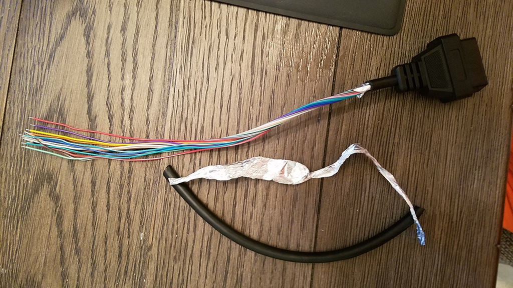 Stripped sheath and shielding
Alt text: Close-up of wires with the outer sheath and shielding carefully removed, preparing them for the OBD2 to USB wiring process.
4.3. Connecting Wires to the OBD2 Connector
Refer to your wiring diagram to identify the correct pins on the OBD2 connector. Insert the prepared wires into the corresponding pins, ensuring that they are securely seated. If using a soldering iron, solder the wires to the pins, creating a strong and reliable connection. If crimping, use the needle-nose pliers or a crimping tool to secure the wires to the pins.
4.4. Connecting Wires to the USB Connector
Similarly, refer to your wiring diagram to identify the correct pins on the USB connector. Insert the prepared wires into the corresponding pins, ensuring that they are securely seated. Solder or crimp the wires to the pins, creating a strong and reliable connection. Pay close attention to the polarity of the power and ground wires to avoid damaging your computer or device.
4.5. Testing the Connections
Using a multimeter, test the continuity of the wiring to ensure that the connections are correct. Verify that there are no short circuits or open circuits in the wiring. Check the voltage levels on the power and ground wires to ensure that they are within the specified range. If any issues are detected, carefully inspect the wiring and connections to identify and correct the problem.
5. Understanding Wire Pairing and Twisting
Why is wire pairing and twisting recommended in OBD2 to USB wiring?
Wire pairing and twisting are recommended to minimize electromagnetic interference (EMI) and ensure signal integrity in OBD2 to USB wiring. Twisting the wires reduces noise and crosstalk, leading to more reliable data transmission between the vehicle and the diagnostic tool. This technique is particularly important for CAN (Controller Area Network) communication, which is sensitive to signal disturbances.
5.1. Reducing Electromagnetic Interference (EMI)
Electromagnetic interference (EMI) can disrupt the communication between the OBD2 port and the USB device. EMI is caused by electromagnetic fields generated by nearby electronic devices or the vehicle’s own electrical system. By twisting the wires together, the electromagnetic fields tend to cancel each other out, reducing the overall level of interference. Shielded cables can further reduce EMI, but twisting the wires is a simple and effective technique that can be implemented even with unshielded cables.
5.2. Enhancing Signal Integrity
Signal integrity refers to the quality of the electrical signals transmitted through the wires. Poor signal integrity can lead to data errors and communication failures. Twisting the wires helps to maintain a consistent impedance, which is the measure of opposition to the flow of electrical current. A consistent impedance ensures that the signals are transmitted cleanly and without distortion. This is particularly important for high-speed data communication, such as CAN bus communication.
5.3. CAN Bus Communication
CAN (Controller Area Network) bus is a communication protocol used in vehicles to allow different electronic control units (ECUs) to communicate with each other. CAN bus communication is sensitive to signal disturbances, such as EMI and impedance mismatches. By twisting the CAN high and CAN low wires together, the signal quality is improved, reducing the risk of communication errors. According to automotive engineering standards, twisted pair wiring is recommended for CAN bus communication to ensure reliable data transmission.
6. Connecting the Wires to the 4-Pin Connector
What is the proper method for connecting wires to a 4-pin connector in an OBD2 to USB setup?
Connecting wires to a 4-pin connector in an OBD2 to USB setup involves ensuring the wires are properly sized, using the correct crimping or soldering techniques, and inserting the pins into the connector in the correct orientation. This ensures a secure and functional connection for reliable data transmission.
6.1. Wire Sizing and Preparation
The wires used to connect to the 4-pin connector should be appropriately sized for the connector pins. Typically, 22-26 AWG wires are suitable for most OBD2 to USB applications. The wires should be stripped to expose about 1/4 to 1/2 inch of the conductor. If the wires are too thin, they may not make good contact with the connector pins. If the wires are too thick, they may be difficult to insert into the connector.
6.2. Crimping or Soldering
The wires can be connected to the connector pins using either crimping or soldering. Crimping involves using a спеціалізована tool to compress the connector pin around the wire, creating a mechanical and electrical connection. Soldering involves melting solder to create a permanent bond between the wire and the connector pin. Soldering is generally considered to be more reliable than crimping, but it requires more skill and specialized equipment.
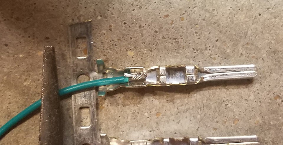
 Connector pin
Alt text: Close-up of a connector pin with visible prongs designed for crimping or soldering, essential for securing wires in a DIY OBD2 to USB wiring setup.
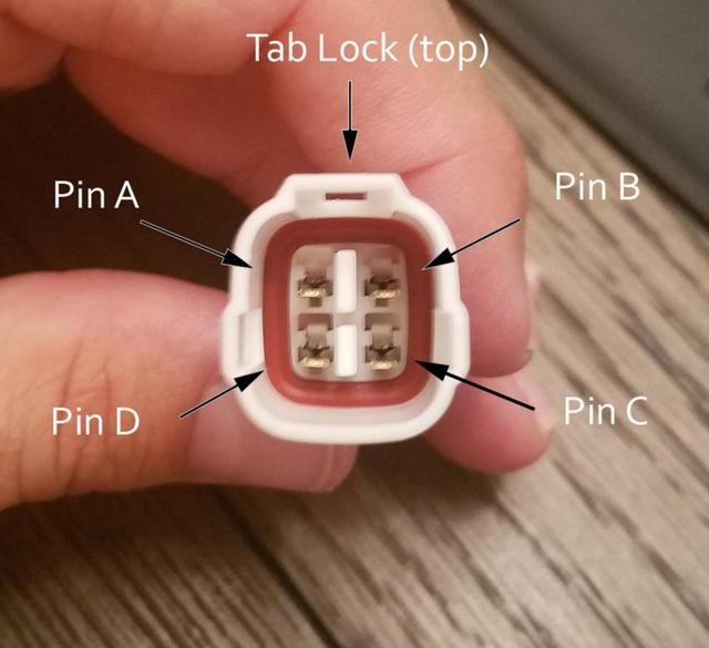
6.3. Inserting Pins into the Connector
The connector pins should be inserted into the 4-pin connector in the correct orientation. Refer to your wiring diagram to identify the correct pin assignments. The pins should be inserted from the rear of the connector until they click into place. Use needle-nose pliers to gently pull on the wires to ensure that the pins are securely locked into the connector.
6.4. Ensuring Secure Connections
Once the pins are inserted into the connector, it’s crucial to ensure they are securely locked in place. Give each wire a gentle tug to confirm that the pins do not come loose. If any pins feel loose, re-insert them and ensure they click audibly into place. A secure connection is vital for reliable data transmission and to prevent intermittent disconnections during use.
7. Testing Your DIY OBD2 to USB Connector
How should you test a DIY OBD2 to USB connector to ensure it functions correctly?
Testing a DIY OBD2 to USB connector involves using a multimeter to check continuity, connecting the adapter to a vehicle and computer with appropriate software, and verifying data transmission. This ensures that the adapter functions correctly and provides reliable access to vehicle diagnostics.
7.1. Continuity Testing with a Multimeter
Before connecting the adapter to your vehicle, use a multimeter to test the continuity of the wiring. Check that there is continuity between the corresponding pins on the OBD2 and USB connectors. Also, check that there are no short circuits between the different pins. This will help to identify any wiring errors before they can cause damage to your vehicle or computer.
7.2. Connecting to a Vehicle and Computer
Connect the OBD2 connector to the OBD2 port on your vehicle. The OBD2 port is typically located under the dashboard, near the steering column. Connect the USB connector to a USB port on your computer. Make sure that your vehicle’s ignition is turned on, but the engine does not need to be running.
7.3. Verifying Data Transmission
Install and launch the OBD2 diagnostic software on your computer. The software should automatically detect the OBD2 adapter and establish a connection to your vehicle’s computer. Verify that the software is able to read data from your vehicle, such as engine speed, coolant temperature, and diagnostic trouble codes. If the software is unable to connect or read data, troubleshoot the wiring and connections to identify the problem.
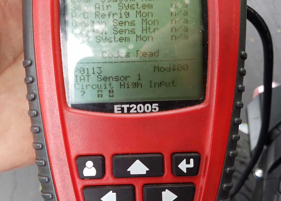 Testing OBD2 connector
Alt text: Image of a successfully tested OBD2 to USB connector displaying error codes, demonstrating the effectiveness of the DIY wiring.
7.4. Using Diagnostic Software
Once connected, use diagnostic software to read and interpret data from your vehicle. Tools like Torque Pro, OBD Auto Doctor, or even Mercedes-specific software can display real-time data such as engine temperature, speed, and fault codes. Ensure that the data is consistent and accurate. If you encounter any issues, double-check your wiring and the software settings to ensure compatibility and proper configuration.
8. Safety Precautions
What safety precautions should be taken when creating and using a DIY OBD2 to USB connector?
When creating and using a DIY OBD2 to USB connector, it’s crucial to follow safety precautions such as disconnecting the vehicle’s battery, using proper grounding techniques, avoiding wiring errors, and using appropriate protective gear. These measures minimize the risk of electrical damage and personal injury.
8.1. Disconnecting the Vehicle’s Battery
Before working on any electrical components in your vehicle, it is important to disconnect the battery. This will help to prevent accidental short circuits or electrical shocks. Disconnect the negative terminal of the battery first, followed by the positive terminal. When reconnecting the battery, connect the positive terminal first, followed by the negative terminal.
8.2. Proper Grounding Techniques
Proper grounding is essential for preventing electrical noise and ensuring the correct operation of the OBD2 adapter. The ground wire should be securely connected to a metal part of the vehicle’s chassis. Avoid connecting the ground wire to painted surfaces, as this can interfere with the connection.
8.3. Avoiding Wiring Errors
Wiring errors can cause serious damage to your vehicle’s electrical system or your computer. Double-check your wiring diagram and connections to ensure that everything is wired correctly. Use a multimeter to verify the continuity of the wiring before connecting the adapter to your vehicle.
8.4. Using Protective Gear
When working with electrical components, it is important to wear appropriate protective gear, such as safety glasses and gloves. Safety glasses will protect your eyes from flying debris or accidental splashes of solder. Gloves will protect your hands from electrical shocks or burns.
9. Troubleshooting Common Issues
What are some common issues encountered when using a DIY OBD2 to USB connector, and how can they be resolved?
Common issues when using a DIY OBD2 to USB connector include connectivity problems, data transmission errors, and software compatibility issues. These problems can often be resolved by checking the wiring, ensuring proper grounding, and updating or configuring the software.
9.1. Connectivity Problems
If the OBD2 adapter is not connecting to your computer or vehicle, the first step is to check the wiring. Ensure that all of the connections are secure and that there are no loose wires. Use a multimeter to verify the continuity of the wiring. Also, check that the OBD2 port on your vehicle is clean and free of debris.
9.2. Data Transmission Errors
If the OBD2 adapter is connecting, but you are experiencing data transmission errors, the problem may be with the grounding. Ensure that the ground wire is securely connected to a metal part of the vehicle’s chassis. Also, check that the OBD2 adapter is not being affected by electromagnetic interference. Try moving the adapter away from other electronic devices or using a shielded USB cable.
9.3. Software Compatibility Issues
If you are experiencing software compatibility issues, ensure that you are using the correct software for your OBD2 adapter and vehicle. Check the software’s documentation or website for compatibility information. Also, ensure that you have the latest drivers installed for your OBD2 adapter.
9.4. Power Supply Problems
A common issue is insufficient power supply to the OBD2 adapter, which can lead to connectivity or data transmission errors. Ensure that the USB port you’re using provides adequate power. Try using a different USB port, or if you’re using a USB hub, connect the adapter directly to the computer. For some vehicles, especially older models, you may need to ensure the vehicle’s battery is fully charged to provide stable power during diagnostics.
10. Benefits of DIY OBD2 to USB Wiring for Mercedes-Benz
What are the specific advantages of creating your own OBD2 to USB wiring for Mercedes-Benz vehicles?
Creating your own OBD2 to USB wiring for Mercedes-Benz vehicles offers several advantages, including cost savings, customized diagnostics, access to advanced features, enhanced learning, and community support. These benefits empower owners to take control of their vehicle’s maintenance and performance.
10.1. Cost Savings
One of the primary benefits of DIY OBD2 to USB wiring is cost savings. Commercial OBD2 scan tools can be expensive, especially those with advanced features and Mercedes-Benz-specific diagnostics. By creating your own adapter, you can save money on the initial purchase and avoid recurring subscription fees for software updates.
10.2. Customized Diagnostics
DIY OBD2 to USB wiring allows you to customize your diagnostic setup to meet your specific needs. You can choose the software and hardware components that best suit your vehicle and diagnostic goals. This level of customization is not possible with off-the-shelf scan tools.
10.3. Access to Advanced Features
With a DIY OBD2 to USB adapter, you can access advanced features that may not be available with standard scan tools. This includes the ability to read and write to the vehicle’s computer, perform custom programming, and unlock hidden features. Access to these advanced features can be valuable for performance tuning, troubleshooting complex issues, and customizing your vehicle’s behavior.
10.4. Enhanced Learning
Creating your own OBD2 to USB adapter is an excellent way to learn about automotive technology and electronics. The process involves understanding wiring diagrams, soldering components, and troubleshooting electrical circuits. This hands-on experience can be valuable for anyone interested in automotive repair or engineering.
10.5. Community Support
There is a large and active online community of DIY OBD2 enthusiasts. These communities provide valuable resources, such as wiring diagrams, software recommendations, and troubleshooting tips. By participating in these communities, you can get help with your DIY project and share your own experiences with others.
11. Advanced Diagnostic and Customization Options
What advanced diagnostic and customization options become available with a DIY OBD2 to USB setup?
A DIY OBD2 to USB setup unlocks advanced diagnostic and customization options for Mercedes-Benz vehicles, including ECU programming, real-time data logging, custom parameter adjustments, and access to hidden features. These capabilities provide deeper insights into vehicle performance and enable personalized enhancements.
11.1. ECU Programming
ECU (Engine Control Unit) programming allows you to modify the software that controls your vehicle’s engine and other systems. With a DIY OBD2 to USB adapter, you can reprogram the ECU to improve performance, fuel economy, or throttle response. ECU programming requires specialized software and a thorough understanding of your vehicle’s systems.
11.2. Real-Time Data Logging
Real-time data logging allows you to monitor your vehicle’s performance parameters in real-time. This can be valuable for troubleshooting performance issues, tracking down intermittent problems, or tuning your vehicle for optimal performance. Data logging software can record parameters such as engine speed, coolant temperature, fuel pressure, and air-fuel ratio.
11.3. Custom Parameter Adjustments
With a DIY OBD2 to USB adapter, you can adjust custom parameters in your vehicle’s computer. This includes parameters such as idle speed, ignition timing, and fuel injection settings. Adjusting these parameters can improve performance, fuel economy, or throttle response. Custom parameter adjustments require specialized software and a thorough understanding of your vehicle’s systems.
11.4. Access to Hidden Features
Many Mercedes-Benz vehicles have hidden features that are not enabled by default. These features can be unlocked with a DIY OBD2 to USB adapter and specialized software. Hidden features may include things like ambient lighting, enhanced display options, or performance-related settings. Unlocking these features can enhance your driving experience and personalize your vehicle to your liking.
12. Cost Savings and DIY Advantages
How does DIY OBD2 to USB wiring compare to professional diagnostic services in terms of cost and benefits?
DIY OBD2 to USB wiring offers significant cost savings compared to professional diagnostic services and provides advantages such as increased control, customization, and learning opportunities. While professional services offer convenience and expertise, DIY solutions empower owners to manage their vehicle’s diagnostics and maintenance independently.
12.1. Comparing Costs
Professional diagnostic services can be expensive, especially for complex issues that require specialized equipment or expertise. A single diagnostic session at a dealership or independent repair shop can cost hundreds of dollars. In contrast, a DIY OBD2 to USB adapter can be created for a fraction of the cost, and the software required for diagnostics is often free or relatively inexpensive.
12.2. Control and Customization
With a DIY OBD2 to USB adapter, you have complete control over your diagnostic setup. You can choose the software and hardware components that best suit your needs and customize the system to your liking. This level of control is not possible with professional diagnostic services, where you are limited to the tools and expertise of the technician.
12.3. Learning Opportunities
Creating and using a DIY OBD2 to USB adapter is an excellent way to learn about automotive technology and electronics. The process involves understanding wiring diagrams, soldering components, and troubleshooting electrical circuits. This hands-on experience can be valuable for anyone interested in automotive repair or engineering.
12.4. Convenience
DIY OBD2 to USB wiring allows you to perform diagnostics and maintenance on your vehicle at your own convenience. You don’t have to schedule an appointment with a mechanic or wait for your vehicle to be serviced. You can perform diagnostics and maintenance whenever you have the time and access to your vehicle.
13. Expert Tips and Recommendations
What expert tips and recommendations can enhance the success of your DIY OBD2 to USB wiring project?
Expert tips for DIY OBD2 to USB wiring include using high-quality components, following wiring diagrams carefully, soldering connections for reliability, testing each connection thoroughly, and consulting online communities for support. These recommendations ensure a successful and reliable DIY project.
13.1. Use High-Quality Components
Using high-quality components is essential for creating a reliable and long-lasting OBD2 to USB adapter. Choose OBD2 and USB connectors from reputable brands that are known for their quality and durability. Use wires that are appropriately sized for the application and that are insulated to prevent short circuits.
13.2. Follow Wiring Diagrams Carefully
Wiring diagrams are essential for ensuring that the OBD2 and USB connectors are wired correctly. Follow the wiring diagrams carefully and double-check your connections before applying power to the adapter. Wiring errors can cause serious damage to your vehicle or computer.
 4-Pin Connector Diagram
Alt text: A detailed diagram illustrating the correct wiring orientation for a 4-Pin Connector in a DIY OBD2 to USB setup, emphasizing precise connections.
13.3. Solder Connections for Reliability
Soldering connections is the most reliable way to ensure that the wires are securely connected to the connector pins. Soldering creates a permanent bond between the wires and the pins, preventing them from coming loose over time. Soldering requires specialized equipment and skill, but it is well worth the effort for the added reliability.
13.4. Test Each Connection Thoroughly
After wiring the OBD2 and USB connectors, test each connection thoroughly with a multimeter. Verify that there is continuity between the corresponding pins on the OBD2 and USB connectors. Also, check that there are no short circuits between the different pins. Testing each connection thoroughly will help to identify any wiring errors before they can cause damage to your vehicle or computer.
13.5. Consult Online Communities for Support
There are many online communities of DIY OBD2 enthusiasts who can provide valuable support and advice. These communities can help you troubleshoot problems, recommend software, and share their own experiences with DIY OBD2 wiring. Participating in these communities is an excellent way to learn more about OBD2 technology and get help with your DIY project.
14. Staying Updated with the Latest Mercedes-Benz Technology
How can Mercedes-Benz owners stay updated on the latest diagnostic and customization techniques?
Mercedes-Benz owners can stay updated on the latest diagnostic and customization techniques by subscribing to industry newsletters, participating in online forums, attending workshops, and regularly visiting MERCEDES-DIAGNOSTIC-TOOL.EDU.VN. This ensures they have access to the most current information and best practices.
14.1. Subscribing to Industry Newsletters
Subscribing to industry newsletters is a great way to receive regular updates on new diagnostic tools, software updates, and customization techniques. Newsletters often provide insights from experts and highlight emerging trends in automotive technology.
14.2. Participating in Online Forums
Online forums are a valuable resource for connecting with other Mercedes-Benz owners and enthusiasts. These forums provide a platform for sharing information, asking questions, and discussing the latest diagnostic and customization techniques.
14.3. Attending Workshops and Training Sessions
Attending workshops and training sessions can provide hands-on experience and in-depth knowledge of Mercedes-Benz diagnostic and customization techniques. These events are often led by experienced technicians and industry experts.
14.4. Regularly Visiting MERCEDES-DIAGNOSTIC-TOOL.EDU.VN
MERCEDES-DIAGNOSTIC-TOOL.EDU.VN provides the latest information on Mercedes-Benz diagnostic tools, software, and customization techniques. Our website is regularly updated with new articles, tutorials, and product reviews. By visiting our website regularly, you can stay informed about the latest developments in Mercedes-Benz technology.
15. Frequently Asked Questions (FAQ)
What are some frequently asked questions about DIY OBD2 to USB wiring, and what are the answers?
This section addresses common questions about DIY OBD2 to USB wiring, including the required tools, compatible software, safety precautions, troubleshooting steps, and benefits. These FAQs provide quick and informative answers to help users successfully complete their DIY projects.
Q1: What tools do I need to create a DIY OBD2 to USB adapter?
A1: You will need wire strippers/cutters, needle-nose pliers, a soldering iron (recommended), a multimeter, an OBD2 connector, a USB connector, and appropriately sized wires.
Q2: What software is compatible with a DIY OBD2 to USB adapter?
A2: Many OBD2 diagnostic software programs are compatible, including Torque Pro, OBD Auto Doctor, and Mercedes-specific software like XENTRY.
Q3: What safety precautions should I take when creating and using a DIY OBD2 to USB adapter?
A3: Disconnect the vehicle’s battery, use proper grounding techniques, avoid wiring errors, and wear appropriate protective gear.
Q4: How can I troubleshoot connectivity problems with my DIY OBD2 to USB adapter?
A4: Check the wiring for loose connections, ensure proper grounding, and verify software compatibility.
Q5: What are the benefits of creating my own OBD2 to USB adapter?
A5: Cost savings, customized diagnostics, access to advanced features, enhanced learning, and community support.
Q6: Can I use a DIY OBD2 to USB adapter to reprogram my Mercedes-Benz ECU?
A6: Yes, but ECU programming requires specialized software, expertise, and a thorough understanding of your vehicle’s systems.
Q7: How do I ensure that my wiring connections are secure and reliable?
A7: Solder the connections for the best reliability and use a multimeter to test for continuity and shorts.
Q8: What wire gauge should I use for my OBD2 to USB wiring?
A8: Typically, 22-26 AWG (American Wire Gauge) wires are suitable for most OBD2 to USB applications.
Q9: How do I access hidden features on my Mercedes-Benz using a DIY OBD2 to USB adapter?
A9: You’ll need specialized software and knowledge of your vehicle’s systems to unlock hidden features, which may include ambient lighting or enhanced display options.
Q10: Where can I find reliable wiring diagrams for my specific Mercedes-Benz model?
A10: Consult online communities, automotive repair manuals, and websites like MERCEDES-DIAGNOSTIC-TOOL.EDU.VN for reliable wiring diagrams and support.
16. Call to Action
Ready to unlock the full potential of your Mercedes-Benz? Contact us at MERCEDES-DIAGNOSTIC-TOOL.EDU.VN for expert guidance on DIY OBD2 to USB wiring, advanced diagnostic tools, and customized solutions. Our team is here to help you diagnose, repair, and enhance your vehicle with confidence.
For personalized assistance, reach out to us:
- Address: 789 Oak Avenue, Miami, FL 33101, United States
- WhatsApp: +1 (641) 206-8880
- Website: MERCEDES-DIAGNOSTIC-TOOL.EDU.VN
Get in touch today and take control of your Mercedes-Benz’s performance and maintenance!