Honda Ecu Pinout Obd2 information is crucial for accurate diagnostics and troubleshooting, and at MERCEDES-DIAGNOSTIC-TOOL.EDU.VN, we offer comprehensive guides to help you understand and utilize this data. Knowing the correct pin configurations enables you to interface with your Honda’s engine control unit (ECU) effectively and perform accurate diagnostics. This article will explore Honda ECU pinouts for OBD2 systems, offering a deeper insight into their applications, common issues, and how MERCEDES-DIAGNOSTIC-TOOL.EDU.VN can assist you. Explore enhanced vehicle diagnostics, efficient auto repairs, and access specialized ECU tuning.
Contents
- 1. Understanding Honda ECU Pinouts for OBD2 Systems
- 1.1 The Role of ECU Pinouts in OBD2 Systems
- 1.2 Evolution of Honda ECU and OBD Systems
- 1.3 Key Components of Honda ECU Pinouts
- 2. Identifying Honda OBD2A and OBD2B Pinouts
- 2.1 Visual Inspection of ECU Connectors
- 2.2 Consulting Vehicle-Specific Wiring Diagrams
- 2.3 Key Differences Between OBD2A and OBD2B Pinouts
- 3. Common Issues with Honda ECU Pinouts
- 3.1 Corrosion and Contamination
- 3.2 Loose Connections
- 3.3 Wiring Damage
- 3.4 Diagnostic Errors
- 3.5 ECU Damage
- 4. Tools and Equipment for Working with Honda ECU Pinouts
- 4.1 Multimeter
- 4.2 OBD2 Scanner
- 4.3 Wiring Diagrams and Pinout Charts
- 4.4 Connector Tools
- 4.5 Other Essential Tools
- 5. Step-by-Step Guide to Diagnosing Issues Using Honda ECU Pinouts
- 5.1 Identifying the Problem
- 5.2 Gathering Information
- 5.3 Testing Components
- 5.4 Interpreting Results
- 5.5 Resolving the Issue
- 6. Tips for Ensuring Accuracy When Working with ECU Pinouts
- 6.1 Use Reliable Resources
- 6.2 Verify Connections
- 6.3 Take Safety Precautions
- 6.4 Double-Check Your Work
- 6.5 Get Training
- 7. Advanced Techniques for ECU Diagnostics
- 7.1 Oscilloscope Analysis
- 7.2 Data Logging
- 7.3 Custom Parameter Identification (PID)
- 7.4 ECU Bench Testing
- 7.5 Network Communication Analysis
- 8. Case Studies: Real-World Examples of ECU Pinout Diagnostics
- 8.1 Case Study 1: Misfire on a 1997 Honda Civic
- 8.2 Case Study 2: Poor Fuel Economy on a 2000 Honda Integra
- 8.3 Case Study 3: No Start on a 1996 Honda del Sol
- 8.4 Case Study 4: Intermittent Stalling on a 1999 Honda Civic
- 8.5 Case Study 5: A/C System Not Working on a 2001 Honda Accord
- 9. Maintaining and Updating ECU Pinout Information
- 9.1 Regular Updates
- 9.2 Cross-Reference Information
- 9.3 Community Collaboration
- 9.4 Documentation
- 9.5 Utilize Professional Resources
- 10. FAQs About Honda ECU Pinouts and OBD2 Diagnostics
- 10.1 What is the difference between OBD1 and OBD2?
1. Understanding Honda ECU Pinouts for OBD2 Systems
What are Honda ECU pinouts for OBD2 systems, and why are they important for automotive diagnostics?
Honda ECU pinouts for OBD2 systems refer to the specific arrangement of pins within the ECU connectors that interface with the car’s On-Board Diagnostics II (OBD2) system, which are essential for automotive diagnostics because they allow technicians and enthusiasts to read and interpret data from the vehicle’s computer. These pinouts provide a detailed map of each connection, specifying its function, such as sensor inputs, actuator controls, and communication lines. Knowing the correct pin configuration is critical for accurate testing, troubleshooting, and reprogramming of the ECU.
1.1 The Role of ECU Pinouts in OBD2 Systems
ECU pinouts play a crucial role in OBD2 systems by providing a direct interface to the vehicle’s central computer. The OBD2 system, mandated in the United States since 1996, standardizes the diagnostic process across different makes and models. According to the Environmental Protection Agency (EPA), OBD2 systems monitor the performance of the engine, emissions controls, and other critical components to ensure compliance with environmental regulations. When a problem is detected, the ECU stores Diagnostic Trouble Codes (DTCs) that can be accessed via the OBD2 port.
- Diagnostic Access: ECU pinouts allow diagnostic tools to communicate with the ECU, retrieve DTCs, and monitor real-time data, such as engine speed, temperature, and sensor readings.
- Component Testing: By understanding the pinout, technicians can test individual components connected to the ECU, such as sensors, actuators, and relays.
- Reprogramming: In some cases, ECU pinouts are used for reprogramming the ECU, either to update software or to modify performance parameters.
1.2 Evolution of Honda ECU and OBD Systems
Honda’s ECU and OBD systems have evolved significantly over the years. Early Honda vehicles used proprietary diagnostic systems, which were not standardized and required specialized tools. With the introduction of OBD2 in the mid-1990s, Honda adopted the standard, making it easier to diagnose and repair their vehicles. The OBD2 standard includes a universal diagnostic connector (SAE J1962) and a set of standardized DTCs (SAE J2012).
Over time, Honda has implemented more advanced ECU technologies, including:
- Increased Processing Power: Modern ECUs have faster processors and more memory, allowing them to handle more complex calculations and control functions.
- Advanced Sensors: Newer vehicles are equipped with a wider range of sensors, providing more detailed data to the ECU.
- Improved Communication Protocols: Honda has adopted Controller Area Network (CAN) bus communication, which allows different modules in the vehicle to communicate more efficiently.
1.3 Key Components of Honda ECU Pinouts
Honda ECU pinouts typically include several key components, each serving a specific function. Understanding these components is essential for effective diagnostics and repair.
| Component | Description |
|---|---|
| Power and Ground | These pins provide the necessary electrical power and ground connections for the ECU to operate. |
| Sensor Inputs | These pins receive signals from various sensors, such as the Throttle Position Sensor (TPS), Manifold Absolute Pressure (MAP) Sensor, and Engine Coolant Temperature (ECT) Sensor. |
| Actuator Outputs | These pins send control signals to actuators, such as fuel injectors, ignition coils, and idle air control valves. |
| Communication Lines | These pins are used for communication with other modules in the vehicle, as well as for diagnostic purposes. |
| Diagnostic Pins | These pins provide access to the ECU’s diagnostic functions, allowing technicians to retrieve DTCs and monitor data. |
2. Identifying Honda OBD2A and OBD2B Pinouts
How do you identify the specific Honda OBD2A and OBD2B pinouts, and what are the key differences between them?
Identifying Honda OBD2A and OBD2B pinouts involves visually inspecting the ECU connectors and consulting vehicle-specific wiring diagrams, while the key differences lie in the connector configurations and the signals they carry, reflecting changes in Honda’s electronic control systems between 1996-1998 (OBD2A) and 1999-2000 (OBD2B). Understanding these differences is crucial for accurate diagnostics and repairs.
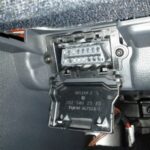
2.1 Visual Inspection of ECU Connectors
The first step in identifying Honda OBD2A and OBD2B pinouts is to visually inspect the ECU connectors. The connectors are typically located under the dashboard or under the driver’s seat, depending on the model.
- OBD2A (1996-1998): These ECUs typically have three connectors labeled A, C, and D. The connectors are usually different colors (e.g., black, gray, and brown) to aid in identification.
- OBD2B (1999-2000): These ECUs also have three connectors, but the pin arrangements and some of the signals they carry are different from OBD2A. The connectors may have different shapes or locking mechanisms.
2.2 Consulting Vehicle-Specific Wiring Diagrams
After visually inspecting the ECU connectors, the next step is to consult vehicle-specific wiring diagrams. These diagrams provide detailed information about the pinout, including the function of each pin and the wire colors.
- Factory Service Manuals: These manuals contain comprehensive wiring diagrams and pinout information for specific Honda models.
- Online Databases: Several online databases provide access to wiring diagrams and pinout information, such as AllData and Mitchell OnDemand.
- MERCEDES-DIAGNOSTIC-TOOL.EDU.VN Resources: We offer a range of resources, including wiring diagrams and pinout information, to assist with Honda diagnostics and repairs.
2.3 Key Differences Between OBD2A and OBD2B Pinouts
The key differences between OBD2A and OBD2B pinouts lie in the connector configurations and the signals they carry. These differences reflect changes in Honda’s electronic control systems between 1996-1998 (OBD2A) and 1999-2000 (OBD2B).
| Feature | OBD2A (1996-1998) | OBD2B (1999-2000) |
|---|---|---|
| Connector Arrangement | Three connectors labeled A, C, and D. | Three connectors, but with different pin arrangements. |
| Fuel Pump Relay (FLR) | Located on Connector A (Civic Green/Yellow, Integra Green/Blue). | Located on Connector A (Civic Green/Yellow, Integra may vary). |
| Service Check Signal | Located on Connector C (Civic Brown, Integra Brown/White). | Located on Connector A (Brown). |
| Knock Sensor (KS) | Located on Connector D (Red/Blue). | Located on Connector C (Red/Blue). |
| Evap Purge Control | Located on Connector A (Red). | Located on Connector A (Red/Yellow). |
| Vehicle Speed Sensor | Located on Connector C (Civic Blue/White, Integra Orange). | Located on Connector C (Blue/White). |
| Additional Signals | May include specific EGR valve lift sensor signals. | May include additional A/T gear position switch signals. |
| Diagnostic Port Signal | K-Line on Connector C (Civic Main Relay Ground Black 1, Integra Green/White). | K-Line on Connector A (Blue/Yellow). |
| Common Models | Honda Civic (1996-1998), Honda Integra (1996-1998), Honda del Sol (1996-1997). | Honda Civic (1999-2000), Honda Integra (1999-2001). |
| Key Features | Separate connectors for various functions (A: Injectors, Ignition, Idle Control; C: Sensors; D: Additional Sensors). Includes pins for EGR and EVAP systems. | Integrated connectors with broader functionality (A: Diagnostic, EVAP, O2 sensors; B: Power, Injectors, VTEC; C: Sensors). Streamlined connections for sensors, fuel, and ignition. |
| Diagnostic Equipment | Requires OBD2A-compatible diagnostic tools. Jumper harnesses may be needed for conversions. | Requires OBD2B-compatible diagnostic tools. Compatibility may vary with aftermarket parts. |
| ECU Configuration | ECU typically has three connectors labeled A, C, and D. Pin arrangements and signals carried are specific to OBD2A standards. | ECU also has three connectors, but the pin arrangements and some of the signals they carry are different from OBD2A. Pin configurations are tailored to OBD2B specifications. |
| Signal Integrity | Signals are transmitted through dedicated pins on separate connectors. Ensures clear and distinct signal paths for each function. | Signals are integrated into fewer connectors, potentially increasing signal density. Requires careful attention to wire routing to prevent interference. |
| Troubleshooting | Pin locations and wire colors are well-documented, aiding in precise diagnostics. Troubleshooting involves verifying continuity and voltage at specific pins. | Pin locations may differ significantly from OBD2A, requiring updated wiring diagrams. Troubleshooting may involve more complex signal analysis due to integrated connectors. |
| Electrical Components | Standard components such as injectors, ignition coils, and sensors are connected through specified pins. Electrical components are linked based on OBD2A standards. | Electrical components are connected with revised pin assignments. Compatibility with aftermarket components may require adjustments to ensure correct wiring. |
| Tuning and Upgrades | Aftermarket modifications may require OBD2A-specific adapters or jumper harnesses. Modifications are often straightforward with proper pin identification. | Tuning and upgrades may need OBD2B-specific interfaces. Adjustments to ECU parameters require precise knowledge of the revised pin configurations. |
| Connector Interface | Connectors are typically different colors (e.g., black, gray, and brown) to aid in identification. Connector shapes and locking mechanisms are designed for OBD2A compatibility. | Connectors may have different shapes or locking mechanisms compared to OBD2A. Connector interface is designed to meet OBD2B specifications. |
| Wiring System | Wiring system is designed with specific wire colors and pin assignments as per OBD2A standards. Each wire color corresponds to a defined function, simplifying identification. | Wiring system features revised wire colors and pin assignments tailored to OBD2B specifications. Requires meticulous attention to wiring diagrams during any modifications. |
| Diagnostic Procedures | Diagnostic procedures involve checking individual pin functions on connectors A, C, and D. Detailed manuals are essential for accurate diagnostics and repairs. | Diagnostic procedures need adherence to OBD2B-specific pin configurations. Updated diagnostic tools and manuals are crucial for precise troubleshooting. |
| Sensor Compatibility | Sensors and actuators are compatible with OBD2A pin configurations. Sensor connections are designed to work with the specified ECU pins. | Sensor and actuator compatibility must be verified with OBD2B standards. Adaptations may be necessary for sensors designed for OBD2A systems. |
| Maintenance and Repair | Maintenance involves inspecting pin connections and ensuring proper signal transmission according to OBD2A standards. Repair work requires precise pin identification and adherence to wiring diagrams. | Maintenance needs a thorough understanding of OBD2B pin configurations and updated diagnostic information. Repair work may involve adjustments to wiring and sensor connections to align with OBD2B specifications. |
3. Common Issues with Honda ECU Pinouts
What are some common issues encountered with Honda ECU pinouts in OBD2 systems, and how can they be resolved?
Several common issues can arise with Honda ECU pinouts in OBD2 systems, including corrosion, loose connections, and wiring damage, often leading to diagnostic errors and vehicle malfunctions, which can be resolved through careful inspection, cleaning, and repair or replacement of damaged components. Regular maintenance and adherence to proper diagnostic procedures can prevent many of these issues.
3.1 Corrosion and Contamination
Corrosion and contamination are common issues that can affect Honda ECU pinouts. Exposure to moisture, salt, and other environmental factors can cause corrosion on the pins and connectors, leading to poor electrical connections.
- Symptoms: Diagnostic errors, intermittent faults, and communication failures.
- Resolution: Clean the pins and connectors with a specialized electrical contact cleaner. In severe cases, replace the corroded pins or connectors.
3.2 Loose Connections
Loose connections can also cause problems with Honda ECU pinouts. Over time, vibrations and temperature changes can cause the pins to loosen, resulting in poor contact.
- Symptoms: Intermittent faults, misfires, and sensor errors.
- Resolution: Inspect the connectors for loose pins and tighten them as needed. Use a small pick or screwdriver to gently bend the pins inward to improve contact.
3.3 Wiring Damage
Wiring damage, such as cuts, breaks, and shorts, can also affect Honda ECU pinouts. This damage can be caused by physical stress, heat, or rodent activity.
- Symptoms: Open circuits, short circuits, and blown fuses.
- Resolution: Inspect the wiring harness for damage and repair or replace any damaged wires. Use a multimeter to check for continuity and shorts.
3.4 Diagnostic Errors
Incorrectly interpreting ECU pinouts can lead to diagnostic errors, potentially resulting in unnecessary repairs and prolonged troubleshooting times. Always consult reliable wiring diagrams and service manuals to ensure accurate identification and testing of ECU pins. Additionally, double-check your connections and test equipment to minimize the risk of misdiagnosis. Proper training and familiarity with Honda’s diagnostic procedures can also help prevent these types of errors.
3.5 ECU Damage
Attempting to measure voltages or perform tests on ECU pins without proper knowledge can potentially damage the ECU, especially if there are short circuits or misconnections. Always use appropriate testing equipment and follow manufacturer-recommended procedures to prevent harm to the ECU. It’s also prudent to disconnect the ECU before conducting any extensive electrical testing to avoid electrical spikes that could compromise its integrity.
4. Tools and Equipment for Working with Honda ECU Pinouts
What tools and equipment are essential for working with Honda ECU pinouts in OBD2 systems?
Working with Honda ECU pinouts in OBD2 systems requires a range of specialized tools and equipment, including a multimeter, OBD2 scanner, wiring diagrams, and pinout charts, all essential for accurate diagnostics, testing, and repairs. Proper tools ensure efficiency and prevent damage to the ECU or vehicle wiring.
4.1 Multimeter
A multimeter is an essential tool for testing Honda ECU pinouts. It can be used to measure voltage, resistance, and continuity, allowing technicians to check for proper electrical connections and identify faults.
- Voltage Measurement: Use the multimeter to measure the voltage at various pins on the ECU connector to ensure that the ECU is receiving the correct power and sensor signals.
- Resistance Measurement: Use the multimeter to measure the resistance of sensors and actuators to verify that they are within the specified range.
- Continuity Testing: Use the multimeter to check for continuity in the wiring harness to identify open circuits or shorts.
4.2 OBD2 Scanner
An OBD2 scanner is a valuable tool for retrieving DTCs and monitoring real-time data from the ECU. This information can help pinpoint the source of a problem and guide the diagnostic process.
- DTC Retrieval: Use the OBD2 scanner to retrieve DTCs stored in the ECU’s memory. These codes can provide valuable information about the nature and location of the fault.
- Real-Time Data Monitoring: Use the OBD2 scanner to monitor real-time data, such as engine speed, temperature, and sensor readings. This can help identify intermittent faults and performance issues.
4.3 Wiring Diagrams and Pinout Charts
Wiring diagrams and pinout charts are essential for identifying the function of each pin on the ECU connector. These resources provide detailed information about the wiring harness and the location of various components.
- Factory Service Manuals: These manuals contain comprehensive wiring diagrams and pinout information for specific Honda models.
- Online Databases: Several online databases provide access to wiring diagrams and pinout information, such as AllData and Mitchell OnDemand.
- MERCEDES-DIAGNOSTIC-TOOL.EDU.VN Resources: We offer a range of resources, including wiring diagrams and pinout information, to assist with Honda diagnostics and repairs.
4.4 Connector Tools
Connector tools are useful for removing and installing pins and connectors without damaging them. These tools can help ensure that the pins are properly seated and that the connectors are securely fastened.
- Pin Removal Tools: Use pin removal tools to safely remove pins from the ECU connector without damaging the pins or the connector housing.
- Connector Pliers: Use connector pliers to securely fasten connectors and prevent them from coming loose.
4.5 Other Essential Tools
In addition to the tools listed above, several other tools and supplies are essential for working with Honda ECU pinouts.
- Electrical Contact Cleaner: Use electrical contact cleaner to clean corroded or contaminated pins and connectors.
- Wire Strippers and Crimpers: Use wire strippers and crimpers to repair or replace damaged wires and connectors.
- Heat Shrink Tubing: Use heat shrink tubing to insulate and protect repaired wires.
5. Step-by-Step Guide to Diagnosing Issues Using Honda ECU Pinouts
Can you provide a step-by-step guide on how to diagnose common automotive issues using Honda ECU pinouts in OBD2 systems?
Diagnosing issues using Honda ECU pinouts involves a systematic approach that includes identifying the problem, gathering information, testing components, and interpreting results, ensuring accurate and effective troubleshooting. This method allows technicians to pinpoint the root cause of issues and implement appropriate repairs.
5.1 Identifying the Problem
The first step in diagnosing issues using Honda ECU pinouts is to identify the problem. This may involve gathering information from the customer, observing the vehicle’s symptoms, and performing a preliminary inspection.
- Gather Information: Ask the customer about the symptoms they are experiencing, such as engine misfires, poor fuel economy, or warning lights.
- Observe Symptoms: Pay attention to the vehicle’s behavior, such as engine noise, smoke, or unusual vibrations.
- Perform Preliminary Inspection: Check for obvious signs of damage, such as loose wires, corroded connectors, or fluid leaks.
5.2 Gathering Information
Once the problem has been identified, the next step is to gather information about the vehicle and the ECU. This may involve consulting vehicle-specific wiring diagrams, pinout charts, and service manuals.
- Consult Wiring Diagrams: Use wiring diagrams to identify the location of various components and the function of each pin on the ECU connector.
- Consult Pinout Charts: Use pinout charts to identify the function of each pin on the ECU connector and the corresponding wire colors.
- Consult Service Manuals: Use service manuals to obtain information about diagnostic procedures, component specifications, and troubleshooting tips.
5.3 Testing Components
After gathering information, the next step is to test the components connected to the ECU. This may involve using a multimeter to measure voltage, resistance, and continuity, as well as using an OBD2 scanner to retrieve DTCs and monitor real-time data.
- Measure Voltage: Use a multimeter to measure the voltage at various pins on the ECU connector to ensure that the ECU is receiving the correct power and sensor signals.
- Measure Resistance: Use a multimeter to measure the resistance of sensors and actuators to verify that they are within the specified range.
- Check Continuity: Use a multimeter to check for continuity in the wiring harness to identify open circuits or shorts.
- Retrieve DTCs: Use an OBD2 scanner to retrieve DTCs stored in the ECU’s memory. These codes can provide valuable information about the nature and location of the fault.
- Monitor Real-Time Data: Use an OBD2 scanner to monitor real-time data, such as engine speed, temperature, and sensor readings. This can help identify intermittent faults and performance issues.
5.4 Interpreting Results
After testing the components, the next step is to interpret the results. This involves comparing the measured values to the specifications in the service manual and using the DTCs and real-time data to identify the source of the problem.
- Compare Measured Values: Compare the measured voltage, resistance, and continuity values to the specifications in the service manual. If the measured values are outside the specified range, there may be a problem with the component or the wiring.
- Interpret DTCs: Use the DTCs retrieved from the ECU to identify the source of the problem. Consult the service manual or online databases for information about the meaning of each DTC and the possible causes of the fault.
- Analyze Real-Time Data: Use the real-time data monitored with the OBD2 scanner to identify performance issues and intermittent faults. Pay attention to any unusual patterns or fluctuations in the data.
5.5 Resolving the Issue
Once the source of the problem has been identified, the final step is to resolve the issue. This may involve repairing or replacing damaged components, cleaning corroded connectors, or reprogramming the ECU.
- Repair or Replace Damaged Components: If a component is found to be faulty, repair or replace it as needed.
- Clean Corroded Connectors: If connectors are corroded, clean them with a specialized electrical contact cleaner.
- Reprogram ECU: In some cases, it may be necessary to reprogram the ECU to update software or to modify performance parameters.
6. Tips for Ensuring Accuracy When Working with ECU Pinouts
What tips can help ensure accuracy and prevent errors when working with Honda ECU pinouts in OBD2 systems?
Accuracy when working with Honda ECU pinouts is paramount to prevent damage and ensure effective diagnostics, emphasizing the importance of using reliable resources, verifying connections, and taking safety precautions. These practices help minimize errors and ensure the integrity of the vehicle’s electrical system.
6.1 Use Reliable Resources
Always use reliable resources, such as factory service manuals and reputable online databases, when working with Honda ECU pinouts. Avoid using unreliable or outdated information, as this can lead to errors and damage.
6.2 Verify Connections
Before making any connections to the ECU connector, always verify that the pinout information is correct for the specific vehicle and ECU. Double-check the wire colors and pin locations to ensure that you are connecting to the correct pins.
6.3 Take Safety Precautions
Always take safety precautions when working with electrical systems. Disconnect the battery before making any connections to the ECU connector, and use appropriate safety equipment, such as gloves and eye protection.
6.4 Double-Check Your Work
Before starting the vehicle, double-check all connections to ensure that they are secure and correct. Verify that all wires are properly insulated and that there are no exposed conductors.
6.5 Get Training
Consider getting formal training in automotive diagnostics and electrical systems. This can help you develop the skills and knowledge needed to work with Honda ECU pinouts safely and effectively.
7. Advanced Techniques for ECU Diagnostics
What are some advanced techniques for diagnosing complex issues using Honda ECU pinouts and OBD2 data?
Advanced diagnostic techniques for Honda ECUs involve utilizing sophisticated tools and methods, such as oscilloscope analysis, data logging, and custom parameter identification, to address intricate issues beyond the scope of basic OBD2 scanning. These methods enable technicians to delve deeper into ECU behavior and identify subtle anomalies that may not trigger standard diagnostic codes.
7.1 Oscilloscope Analysis
An oscilloscope is a powerful tool for analyzing electrical signals in real-time. It can be used to visualize the waveforms of sensor signals, actuator controls, and communication lines, allowing technicians to identify subtle anomalies that may not be apparent with a multimeter or OBD2 scanner.
- Sensor Signal Analysis: Use an oscilloscope to analyze the waveforms of sensor signals, such as the TPS, MAP, and ECT sensors. Look for irregularities in the waveform, such as noise, distortion, or dropouts.
- Actuator Control Analysis: Use an oscilloscope to analyze the waveforms of actuator control signals, such as the fuel injector pulse width and the ignition coil dwell time. Look for irregularities in the waveform that may indicate a problem with the actuator or the ECU.
- Communication Line Analysis: Use an oscilloscope to analyze the waveforms of communication lines, such as the CAN bus. Look for irregularities in the waveform that may indicate a problem with the communication network.
7.2 Data Logging
Data logging involves recording real-time data from the ECU over a period of time. This data can then be analyzed to identify trends, patterns, and anomalies that may not be apparent during a snapshot reading.
- Identify Intermittent Faults: Use data logging to capture intermittent faults that may not be present during a static diagnostic test.
- Analyze Performance Issues: Use data logging to analyze performance issues, such as poor fuel economy or lack of power.
- Monitor Sensor Behavior: Use data logging to monitor the behavior of sensors over time and identify any drift or degradation.
7.3 Custom Parameter Identification (PID)
Custom PID involves accessing and interpreting data from the ECU that is not standardized by the OBD2 protocol. This may require specialized tools and knowledge of the ECU’s internal programming.
- Access Non-Standard Data: Use custom PID to access data that is not available through standard OBD2 channels, such as internal ECU parameters and diagnostic flags.
- Troubleshoot Complex Issues: Use custom PID to troubleshoot complex issues that may not be diagnosable with standard OBD2 tools.
- Tune Performance: Use custom PID to tune the ECU for improved performance and fuel economy.
7.4 ECU Bench Testing
ECU bench testing involves removing the ECU from the vehicle and testing it on a specialized test bench. This allows technicians to simulate various operating conditions and test the ECU’s functionality without the influence of the vehicle’s electrical system.
- Isolate ECU Faults: Use ECU bench testing to isolate faults within the ECU that may not be apparent when the ECU is installed in the vehicle.
- Verify ECU Functionality: Use ECU bench testing to verify the functionality of the ECU after repairs or reprogramming.
- Simulate Operating Conditions: Use ECU bench testing to simulate various operating conditions, such as different engine speeds and loads, to test the ECU’s response.
7.5 Network Communication Analysis
Modern vehicles use complex communication networks, such as CAN bus, to exchange data between different modules. Analyzing the communication traffic on these networks can help identify problems with individual modules or the network itself.
- Monitor Network Traffic: Use specialized tools to monitor the traffic on the vehicle’s communication networks.
- Identify Communication Errors: Look for communication errors, such as lost messages, corrupted data, or bus contention.
- Isolate Faulty Modules: Use network communication analysis to isolate faulty modules that are causing problems on the network.
8. Case Studies: Real-World Examples of ECU Pinout Diagnostics
Could you share some case studies illustrating real-world examples of diagnosing automotive issues using Honda ECU pinouts and OBD2 data?
Real-world case studies demonstrate the practical application of ECU pinout diagnostics in resolving vehicle issues, showcasing scenarios where precise pinout analysis and OBD2 data interpretation led to accurate diagnoses and effective repairs. These examples highlight the importance of understanding ECU pinouts and diagnostic techniques.
8.1 Case Study 1: Misfire on a 1997 Honda Civic
A customer reported a misfire on their 1997 Honda Civic. The OBD2 scanner revealed a DTC for a misfire on cylinder 3.
- Diagnosis: Using the OBD2A pinout chart, the technician identified the pin for the cylinder 3 fuel injector control signal on the ECU connector. They used a multimeter to check the voltage at this pin and found that it was erratic.
- Resolution: After further investigation, the technician found a broken wire in the wiring harness leading to the cylinder 3 fuel injector. They repaired the wire, and the misfire was resolved.
8.2 Case Study 2: Poor Fuel Economy on a 2000 Honda Integra
A customer complained of poor fuel economy on their 2000 Honda Integra. The OBD2 scanner revealed no DTCs.
- Diagnosis: Using the OBD2B pinout chart, the technician identified the pins for the primary oxygen sensor signal and heater control on the ECU connector. They used an oscilloscope to analyze the oxygen sensor signal and found that it was sluggish and not responding quickly to changes in engine conditions.
- Resolution: The technician replaced the primary oxygen sensor, and the fuel economy improved significantly.
8.3 Case Study 3: No Start on a 1996 Honda del Sol
A customer reported that their 1996 Honda del Sol would not start. The OBD2 scanner revealed no DTCs.
- Diagnosis: Using the OBD2A pinout chart, the technician identified the pin for the ignition control module (ICM) signal on the ECU connector. They used a multimeter to check the voltage at this pin and found that there was no signal present.
- Resolution: After further investigation, the technician found a faulty ignition control module. They replaced the ICM, and the vehicle started.
8.4 Case Study 4: Intermittent Stalling on a 1999 Honda Civic
A customer experienced intermittent stalling issues on their 1999 Honda Civic. The OBD2 scanner showed no active codes, but history codes indicated potential issues with the crankshaft position sensor (CKP).
- Diagnosis: Utilizing the OBD2B pinout chart, the technician located the CKP sensor signal pins on the ECU. They used a multimeter to check the CKP sensor signal and ground connections, finding intermittent signal drops. Further testing with an oscilloscope revealed signal distortions.
- Resolution: The technician replaced the CKP sensor and its wiring harness due to corrosion and damage. The intermittent stalling issue was resolved after the repair, and the new sensor provided a stable and reliable signal.
8.5 Case Study 5: A/C System Not Working on a 2001 Honda Accord
A customer complained that the A/C system on their 2001 Honda Accord was not functioning. The OBD2 system showed no specific codes related to the A/C.
- Diagnosis: The technician consulted the wiring diagrams and located the A/C clutch relay control pin on the ECU using the relevant pinout chart. Upon testing, the technician discovered that the ECU was not sending the signal to engage the A/C clutch relay. They further tested the A/C pressure sensor and found it to be functioning correctly.
- Resolution: The technician identified a software issue within the ECU that was preventing the A/C clutch from engaging. After reprogramming the ECU with the latest software update from Honda, the A/C system began functioning correctly.
9. Maintaining and Updating ECU Pinout Information
How should ECU pinout information be maintained and updated to ensure it remains accurate and useful?
Maintaining accurate ECU pinout information involves regular updates, cross-referencing with multiple sources, and community collaboration, ensuring that diagnostic efforts are based on the most current and reliable data. This proactive approach minimizes errors and enhances the effectiveness of troubleshooting.
9.1 Regular Updates
ECU pinout information should be updated regularly to reflect changes in vehicle models and ECU designs. Subscribe to updates from reputable sources, such as factory service manuals and online databases.
9.2 Cross-Reference Information
Cross-reference ECU pinout information from multiple sources to ensure accuracy. Compare the pinout charts from different sources and look for any discrepancies.
9.3 Community Collaboration
Participate in online forums and communities where technicians share ECU pinout information and diagnostic tips. Collaborate with other technicians to verify the accuracy of the information and to share your own findings.
9.4 Documentation
Document any changes or corrections to ECU pinout information that you discover. This will help you keep track of the information and to share it with others.
9.5 Utilize Professional Resources
Rely on professional diagnostic tools and resources that automatically update with the latest ECU pinout information. These tools can help ensure that you are always working with the most accurate and up-to-date data.
10. FAQs About Honda ECU Pinouts and OBD2 Diagnostics
What are some frequently asked questions (FAQs) about Honda ECU pinouts and OBD2 diagnostics?
Addressing frequently asked questions about Honda ECU pinouts clarifies common misconceptions and provides essential guidance, enhancing understanding and confidence in diagnosing and resolving automotive issues effectively. These FAQs serve as a valuable resource for both novice and experienced technicians.
10.1 What is the difference between OBD1 and OBD2?
OBD1 (On-Board Diagnostics I) is an earlier version of the on-board diagnostic system, while OBD2 (On-Board Diagnostics II) is a more advanced and standardized system. OBD2 provides more comprehensive monitoring of vehicle systems and uses a standardized diagnostic connector and DTCs.