Making an OBD1 to OBD2 adapter harness allows you to connect newer diagnostic tools to older vehicles. At MERCEDES-DIAGNOSTIC-TOOL.EDU.VN, we simplify this process, providing you with expert guidance on building your own adapter. This ensures compatibility and efficient diagnostics, saving you time and money while enhancing your vehicle’s performance. Learn about OBD1 conversion, OBD2 scanner compatibility and auto diagnostic tools.
Contents
- 1. Understanding the Need for an OBD1 to OBD2 Adapter Harness
- 1.1. What is OBD1?
- 1.2. What is OBD2?
- 1.3. Why Convert from OBD1 to OBD2?
- 1.4. Legal and Compatibility Considerations
- 2. Essential Tools and Parts for Creating an OBD1 to OBD2 Adapter Harness
- 2.1. Required Tools
- 2.2. Necessary Parts
- 2.3. Optional but Recommended
- 2.4. Where to Source the Parts
- 2.5. Cost Considerations
- 3. Step-by-Step Guide to Building Your Adapter Harness
- 3.1. Identifying the Correct Pins
- OBD1 Pin Identification
- OBD2 Pin Identification
- Documenting Pin Assignments
- 3.2. Wiring the Connectors
- Stripping the Wires
- Crimping the Pins
- Soldering the Connections (Recommended)
- Insulating the Connections
- 3.3. Testing the Connection
- Continuity Testing
- Voltage Testing
- Troubleshooting
- 4. Pinout Diagrams and Wiring Configurations
- 4.1. Common OBD1 Pinout Diagrams
- 4.2. Standard OBD2 Pinout Diagram
- 4.3. Wiring Configuration Examples
- Example 1: GM ALDL to OBD2
- Example 2: Ford EEC-IV to OBD2
- 4.4. Creating a Custom Wiring Diagram
- 4.5. Using Online Resources
- 5. Potential Issues and Troubleshooting
- 5.1. Common Issues
- 5.2. Troubleshooting Steps
- 5.3. Advanced Troubleshooting
- 6. Advanced Tips and Considerations
- 6.1. Shielding the Wires
- 6.2. Using High-Quality Connectors and Terminals
- 6.3. Implementing Overcurrent Protection
- 6.4. Adding a Status Indicator LED
- 6.5. Ensuring Proper Grounding
- 6.6. Software and Scanner Compatibility
- 6.7. Environmental Considerations
- 6.8. Documenting Your Build
- 7. Alternatives to Building Your Own Adapter Harness
- 7.1. Purchasing a Pre-Made Adapter Harness
- 7.2. Using a Combination OBD1/OBD2 Scanner
- 7.3. Hiring a Professional Technician
- 7.4. Renting a Diagnostic Tool
- 8. Real-World Applications and Case Studies
- 8.1. Diagnosing Vintage Cars
- 8.2. Tuning and Performance Optimization
- 8.3. Emission Testing and Compliance
- 8.4. DIY Repair and Maintenance
- 8.5. Educational and Training Purposes
- 9. Future Trends in Vehicle Diagnostics
- 9.1. Rise of Wireless Diagnostics
- 9.2. Integration of Artificial Intelligence (AI)
- 9.3. Expansion of Telematics and Connected Car Services
- 9.4. Focus on Cybersecurity
- 9.5. Standardization of Diagnostic Protocols
- 9.6. Remote Diagnostics and Over-the-Air (OTA) Updates
- 9.7. Enhanced Data Analytics
- 10. FAQs About OBD1 to OBD2 Adapter Harnesses
- 10.1. What is the difference between OBD1 and OBD2?
- 10.2. Why would I need an OBD1 to OBD2 adapter harness?
- 10.3. What tools are required to build an OBD1 to OBD2 adapter harness?
- 10.4. Can I buy a pre-made OBD1 to OBD2 adapter harness?
- 10.5. What are the common issues when building an adapter harness?
1. Understanding the Need for an OBD1 to OBD2 Adapter Harness
Why is there a need to adapt between OBD1 and OBD2 systems? Older vehicles used the On-Board Diagnostics 1 (OBD1) system, while newer vehicles use the On-Board Diagnostics 2 (OBD2) system. The primary difference lies in the diagnostic capabilities and the connector types. OBD2 offers a standardized connector and more comprehensive data, which is why adapting from OBD1 to OBD2 is beneficial for modern diagnostics.
1.1. What is OBD1?
OBD1, or On-Board Diagnostics 1, refers to the early generation of automotive diagnostic systems implemented in vehicles before the mid-1990s. These systems were less standardized and varied significantly between manufacturers.
- Lack of Standardization: Each car manufacturer had its own diagnostic connector and communication protocol.
- Limited Data: OBD1 systems provided limited diagnostic information, often only indicating basic engine malfunctions.
- Retrieval Methods: Accessing diagnostic codes typically required specialized tools and manufacturer-specific procedures.
1.2. What is OBD2?
OBD2, or On-Board Diagnostics 2, is a standardized system introduced in the mid-1990s to provide more comprehensive and uniform diagnostic information across all vehicles.
- Standardized Connector: OBD2 uses a standard 16-pin Data Link Connector (DLC), making it universally accessible.
- Comprehensive Data: OBD2 systems monitor a wide range of vehicle parameters, including emissions, engine performance, and more.
- Diagnostic Trouble Codes (DTCs): OBD2 provides standardized DTCs, making it easier to identify and troubleshoot issues.
- Real-Time Data: OBD2 allows access to real-time data, enabling technicians to monitor vehicle performance in real time.
1.3. Why Convert from OBD1 to OBD2?
Converting from OBD1 to OBD2 offers several advantages:
- Access to Modern Diagnostic Tools: Allows the use of modern OBD2 scanners and diagnostic equipment.
- Enhanced Diagnostic Capabilities: Provides more detailed and accurate diagnostic information.
- Standardized Interface: Simplifies the diagnostic process with a universal connector and protocol.
- Future-Proofing: Prepares older vehicles for future diagnostic needs and compatibility with newer technologies.
1.4. Legal and Compatibility Considerations
Before converting from OBD1 to OBD2, consider the following:
- Emissions Testing: Ensure the conversion does not interfere with emissions testing requirements in your region.
- Vehicle Compatibility: Verify that the conversion is compatible with your specific vehicle make and model.
- Professional Advice: Consult with a qualified mechanic or technician to ensure proper installation and functionality.
2. Essential Tools and Parts for Creating an OBD1 to OBD2 Adapter Harness
What tools and parts do you need to build an OBD1 to OBD2 adapter harness? You’ll require a few essential tools and parts, including wire strippers, a crimping tool, a soldering iron (optional but recommended), an OBD2 connector, and a compatible OBD1 connector. These items ensure a secure and reliable connection between the two systems.
2.1. Required Tools
- Wire Strippers/Cutters: To strip the insulation from wires without damaging them.
- Needle-Nose Pliers: To grip and manipulate small wires and connectors.
- Crimping Tool: To securely crimp the pins onto the wires. A Molex crimping tool is recommended for optimal results.
- Soldering Iron: To provide a solid and reliable connection between the wires and pins (optional but recommended).
- Multimeter: To test the continuity and voltage of the connections.
- Heat Shrink Tubing: To insulate and protect the soldered or crimped connections.
- Heat Gun: To shrink the heat shrink tubing for a secure fit.
2.2. Necessary Parts
- OBD2 Connector: A standard 16-pin female OBD2 connector. (link to part used)
- OBD1 Connector: A connector that matches the specific OBD1 port on your vehicle. This will vary depending on the make and model of the car.
- Wire: Automotive-grade wire of appropriate gauge (18-22 AWG) to handle the current and voltage requirements.
- Pins/Terminals: Connector pins that are compatible with both the OBD1 and OBD2 connectors.
- Connectors:4-pin connector (link to part used; pin/wire size = 22-16AWG; insulation/seal size = 1.3-1.7mm)
2.3. Optional but Recommended
- Solder: High-quality solder for creating strong and corrosion-resistant connections.
- Flux: Soldering flux to improve the flow and adhesion of solder.
- Helping Hands: A tool to hold wires and connectors in place while soldering.
- Third Hand Tool with Magnifying Glass: Useful for detailed soldering and inspection work.
- Wire Labels: To label each wire to ensure correct connections.
2.4. Where to Source the Parts
- Online Retailers: Websites like Amazon, eBay, and specialized electronics suppliers.
- Automotive Parts Stores: Local auto parts stores often carry OBD connectors and wiring supplies.
- Electronics Suppliers: Companies like Digi-Key or Mouser Electronics for high-quality connectors and terminals.
- Salvage Yards: You may find OBD1 connectors from vehicles in salvage yards, but ensure they are in good condition.
2.5. Cost Considerations
The cost of tools and parts can vary depending on the quality and source. Budget accordingly:
- Basic Tools: $20 – $50
- Connectors and Wiring: $15 – $30
- Soldering Equipment (if needed): $30 – $100
Investing in quality tools and parts ensures a reliable and durable OBD1 to OBD2 adapter harness.
3. Step-by-Step Guide to Building Your Adapter Harness
How do you actually build the OBD1 to OBD2 adapter harness? Creating your own adapter harness involves several key steps: identifying the correct pins, wiring the connectors, and testing the connection. Follow this detailed guide to ensure a successful build.
3.1. Identifying the Correct Pins
Before starting the wiring process, it’s crucial to identify the correct pins on both the OBD1 and OBD2 connectors. Consult your vehicle’s service manual or reliable online resources for accurate pinout diagrams.
OBD1 Pin Identification
- Consult Vehicle-Specific Diagrams: OBD1 pinouts vary significantly by vehicle make and model. Always refer to a vehicle-specific service manual or reliable online database.
- Common OBD1 Pins to Identify:
- Ground: Provides a common ground for the diagnostic system.
- Battery Power: Supplies power to the diagnostic system.
- Diagnostic Data Line: Carries the diagnostic data between the vehicle and the diagnostic tool.
- K-Line/L-Line: Used for communication in some OBD1 systems.
- Use a Multimeter: Use a multimeter to confirm the function of each pin based on the vehicle’s wiring diagram.
OBD2 Pin Identification
The OBD2 connector has a standardized pinout, but it’s still important to verify the pin functions to ensure correct wiring.
- Standard OBD2 Pinout:
- Pin 4: Chassis Ground
- Pin 5: Signal Ground
- Pin 6: CAN High (J-2284)
- Pin 7: K-Line (ISO 9141-2)
- Pin 10: J1850 VPW
- Pin 14: CAN Low (J-2284)
- Pin 15: L-Line (ISO 9141-2)
- Pin 16: Battery Power
- Cross-Reference with OBD1: Match the functions of the OBD2 pins with the corresponding functions on the OBD1 connector based on your vehicle’s diagnostic requirements.
Documenting Pin Assignments
- Create a Wiring Diagram: Draw a simple diagram showing the pin connections between the OBD1 and OBD2 connectors.
- Label Wires: Use wire labels to mark each wire with its corresponding pin number and function.
- Double-Check Your Work: Before making any connections, double-check your pin assignments against the vehicle’s service manual and OBD2 standard to avoid errors.
3.2. Wiring the Connectors
With the pins identified, the next step is to wire the connectors. This involves stripping the wires, crimping or soldering them to the connector pins, and insulating the connections.
Stripping the Wires
- Use Wire Strippers: Use wire strippers to carefully remove the insulation from the ends of the wires without nicking or cutting the wire strands.
- Strip Length: Strip about 1/4 to 1/2 inch of insulation from each wire end.
- Inspect Wires: Check the stripped wires for any damage. Damaged wires can cause poor connections and unreliable data transmission.
Crimping the Pins
- Select Correct Pins: Ensure you have the correct pins for your connectors and wire gauge.
- Insert Wire into Pin: Insert the stripped wire into the crimp pin, making sure the wire strands are fully inserted.
- Use Crimping Tool: Use a crimping tool to securely crimp the pin onto the wire. Ensure the crimp is tight and the wire is firmly held in place.
- Test the Crimp: Gently tug on the wire to ensure it is securely crimped. A good crimp should not allow the wire to pull out.
Soldering the Connections (Recommended)
- Tin the Wires: Apply a small amount of solder to the stripped wire ends to tin them. This helps improve the electrical connection.
- Heat the Pin: Heat the connector pin with the soldering iron.
- Apply Solder: Apply solder to the pin and wire, allowing it to flow and create a solid connection.
- Allow to Cool: Allow the solder to cool and harden before moving the connection.
Insulating the Connections
- Use Heat Shrink Tubing: Slide heat shrink tubing over the soldered or crimped connection.
- Position Tubing: Position the tubing so that it covers the entire connection and extends slightly onto the wire insulation.
- Apply Heat: Use a heat gun to shrink the tubing, providing a secure and insulated covering over the connection.
- Inspect Insulation: Ensure the insulation is tight and fully covers the connection to prevent shorts and corrosion.
3.3. Testing the Connection
After wiring the connectors, it’s essential to test the connection to ensure it is working correctly. Use a multimeter to check for continuity and proper voltage.
Continuity Testing
- Set Multimeter to Continuity Mode: Turn on your multimeter and set it to the continuity testing mode (usually indicated by a diode symbol or a sound wave symbol).
- Test Each Pin: Place one probe of the multimeter on the OBD1 connector pin and the other probe on the corresponding OBD2 connector pin.
- Verify Continuity: The multimeter should indicate continuity (usually with a beep or a reading close to zero ohms) if the connection is good.
- Check All Pins: Repeat this process for all wired pins to ensure each connection is solid.
Voltage Testing
- Connect Adapter to Vehicle: Plug the OBD1 connector into your vehicle’s OBD1 port.
- Set Multimeter to Voltage Mode: Set your multimeter to the appropriate DC voltage range (usually 12V or 20V).
- Test Power Pins: Place the black probe of the multimeter on a known good ground and the red probe on the OBD2 connector’s power pin (Pin 16).
- Verify Voltage: You should read approximately 12V, indicating that power is being supplied correctly.
- Check Other Voltage Pins: Test any other voltage-related pins as necessary.
Troubleshooting
- No Continuity: If you do not get a continuity reading, check the wiring for breaks, loose connections, or poor crimps/solders.
- Incorrect Voltage: If the voltage reading is incorrect, double-check the wiring diagram and ensure that the power and ground wires are connected correctly.
- Short Circuits: Use the multimeter to check for short circuits between adjacent pins. There should be no continuity between pins that are not supposed to be connected.
Following these detailed steps will help you build a reliable and functional OBD1 to OBD2 adapter harness, ensuring accurate diagnostic data and vehicle performance monitoring.
4. Pinout Diagrams and Wiring Configurations
What are the standard pinout diagrams for OBD1 and OBD2, and how do you configure the wiring correctly? Understanding the pinout diagrams and wiring configurations is essential for a successful adapter harness. These diagrams provide a clear map of how each pin on the OBD1 connector corresponds to its counterpart on the OBD2 connector.
4.1. Common OBD1 Pinout Diagrams
OBD1 pinouts vary significantly depending on the vehicle’s make, model, and year. Here are some common examples:
- GM ALDL (Assembly Line Diagnostic Link):
- Pin A: Ground
- Pin B: Diagnostic Data
- Pin E: Serial Data
- Pin M: Battery Power
- Ford EEC-IV (Electronic Engine Control):
- Pin 2: Ground
- Pin 4: Test/Diagnostic Output
- Pin 46: Battery Power
- Chrysler SCI (Single Connector Interface):
- Pin 3: Sensor Ground
- Pin 9: Diagnostic Data
- Pin 12: Battery Power
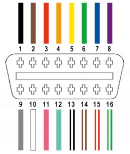
4.2. Standard OBD2 Pinout Diagram
The OBD2 connector has a standardized pinout as specified by SAE J1962:
- Pin 1: Manufacturer Discretion
- Pin 2: J1850 Bus+
- Pin 3: Manufacturer Discretion
- Pin 4: Chassis Ground
- Pin 5: Signal Ground
- Pin 6: CAN High (J-2284)
- Pin 7: K-Line (ISO 9141-2)
- Pin 8: Manufacturer Discretion
- Pin 9: Manufacturer Discretion
- Pin 10: J1850 Bus-
- Pin 11: Manufacturer Discretion
- Pin 12: Manufacturer Discretion
- Pin 13: Manufacturer Discretion
- Pin 14: CAN Low (J-2284)
- Pin 15: L-Line (ISO 9141-2)
- Pin 16: Battery Power
4.3. Wiring Configuration Examples
To create an adapter harness, you need to map the OBD1 pins to the corresponding OBD2 pins. Here are a few examples:
Example 1: GM ALDL to OBD2
- GM ALDL Pin A (Ground) to OBD2 Pin 4 (Chassis Ground) and Pin 5 (Signal Ground)
- GM ALDL Pin B (Diagnostic Data) to OBD2 Pin 7 (K-Line)
- GM ALDL Pin M (Battery Power) to OBD2 Pin 16 (Battery Power)
Example 2: Ford EEC-IV to OBD2
- Ford EEC-IV Pin 2 (Ground) to OBD2 Pin 4 (Chassis Ground) and Pin 5 (Signal Ground)
- Ford EEC-IV Pin 4 (Test/Diagnostic Output) to OBD2 Pin 7 (K-Line)
- Ford EEC-IV Pin 46 (Battery Power) to OBD2 Pin 16 (Battery Power)
4.4. Creating a Custom Wiring Diagram
- Identify Required Signals: Determine which signals from the OBD1 system you need for your diagnostic tool.
- Consult Vehicle-Specific Information: Always refer to the vehicle’s service manual or a reliable online database for accurate pinout information.
- Map the Pins: Create a table or diagram showing the mapping between the OBD1 and OBD2 pins.
- Double-Check Your Work: Before wiring, double-check your pin assignments to avoid errors and potential damage to the vehicle or diagnostic tool.
4.5. Using Online Resources
Several online resources provide pinout diagrams and wiring information for various vehicles:
- Vehicle-Specific Forums: Online forums dedicated to specific vehicle makes and models often have detailed diagnostic information.
- Automotive Diagnostic Databases: Websites like Alldata and Mitchell OnDemand provide comprehensive vehicle information, including pinout diagrams.
- OBD Resource Sites: Websites dedicated to OBD technology often have pinout information for various OBD1 systems.
Understanding the pinout diagrams and wiring configurations is essential for creating a reliable and functional OBD1 to OBD2 adapter harness. Always verify the pin assignments and double-check your work to avoid errors and ensure accurate diagnostic data.
5. Potential Issues and Troubleshooting
What are some common problems you might encounter when building or using an OBD1 to OBD2 adapter harness, and how do you troubleshoot them? Building an adapter harness can present challenges. Addressing these issues promptly ensures a reliable connection and accurate diagnostic readings.
5.1. Common Issues
- Incorrect Pinout:
- Problem: Wiring the wrong pins together can lead to communication errors or damage to the vehicle’s ECU or diagnostic tool.
- Solution: Always double-check the pinout diagrams for both the OBD1 and OBD2 connectors. Verify the pin assignments with a reliable source, such as the vehicle’s service manual.
- Poor Connection Quality:
- Problem: Loose or poorly crimped/soldered connections can cause intermittent communication or complete failure.
- Solution: Ensure all connections are securely crimped or soldered. Use quality crimping tools and solder. Test each connection for continuity with a multimeter.
- Wiring Issues:
- Problem: Damaged or corroded wires can disrupt the signal and cause communication errors.
- Solution: Inspect the wires for any signs of damage. Replace any damaged wires and ensure they are properly insulated. Use automotive-grade wire for better durability.
- Compatibility Issues:
- Problem: Some OBD2 scanners may not be fully compatible with older OBD1 systems, even with an adapter.
- Solution: Research the compatibility of your OBD2 scanner with OBD1 systems. Some scanners may require specific software or settings to work with older vehicles.
- Grounding Problems:
- Problem: Inadequate grounding can cause communication errors or inaccurate readings.
- Solution: Ensure that the ground connections are solid and properly connected to the vehicle’s chassis ground. Use a multimeter to check the resistance between the ground pin and the chassis.
5.2. Troubleshooting Steps
- Check Pinout Accuracy:
- Step 1: Review the pinout diagrams for both the OBD1 and OBD2 connectors.
- Step 2: Verify that the wiring matches the diagrams.
- Step 3: Correct any wiring errors and retest the connection.
- Inspect Connections:
- Step 1: Visually inspect all connections for looseness, corrosion, or damage.
- Step 2: Tug gently on each wire to ensure it is securely connected to the pin.
- Step 3: Re-crimp or re-solder any loose or damaged connections.
- Test Continuity:
- Step 1: Use a multimeter to test the continuity between corresponding pins on the OBD1 and OBD2 connectors.
- Step 2: Ensure that there is a low resistance (close to 0 ohms) between each connected pin.
- Step 3: If there is no continuity, troubleshoot the wiring and connections.
- Check Voltage:
- Step 1: Connect the adapter to the vehicle and turn on the ignition.
- Step 2: Use a multimeter to check the voltage at the OBD2 connector’s power pin (Pin 16).
- Step 3: Verify that the voltage is within the expected range (typically 12-14V).
- Step 4: If the voltage is incorrect, check the power and ground connections.
- Isolate the Problem:
- Step 1: If the adapter is not working, try using it with a different OBD2 scanner or vehicle (if possible) to isolate the problem.
- Step 2: If the adapter works with other devices, the issue may be with the scanner or vehicle.
- Step 3: If the adapter does not work with other devices, the issue is likely with the adapter itself.
5.3. Advanced Troubleshooting
- Use a Logic Analyzer:
- Purpose: A logic analyzer can help you examine the data signals being transmitted between the OBD1 and OBD2 connectors.
- How to Use: Connect the logic analyzer to the diagnostic data lines and monitor the signals for any abnormalities or errors.
- Consult Vehicle-Specific Forums:
- Benefit: Online forums dedicated to specific vehicle makes and models can provide valuable insights and troubleshooting tips.
- Action: Search the forums for similar issues and follow any recommended solutions.
- Seek Professional Help:
- Recommendation: If you are unable to resolve the issue on your own, consider seeking help from a qualified automotive technician or diagnostic specialist.
6. Advanced Tips and Considerations
Are there any advanced tips or considerations to keep in mind for optimizing your OBD1 to OBD2 adapter harness? Optimizing your adapter harness can significantly improve its performance and reliability. Consider these advanced tips for the best results.
6.1. Shielding the Wires
- Purpose: Shielding the wires can reduce electromagnetic interference (EMI) and improve signal integrity, especially in noisy environments.
- How to Implement: Use shielded wire for the diagnostic data lines. Connect the shield to the chassis ground at one end only to avoid ground loops.
6.2. Using High-Quality Connectors and Terminals
- Importance: High-quality connectors and terminals provide better conductivity, durability, and resistance to corrosion.
- Recommendations: Use connectors and terminals from reputable manufacturers. Ensure they are properly rated for automotive use and can withstand temperature variations and vibrations.
6.3. Implementing Overcurrent Protection
- Purpose: Overcurrent protection can protect the vehicle’s ECU and the diagnostic tool from damage in case of a short circuit or other electrical fault.
- How to Implement: Install a fuse in the power line (Pin 16 of the OBD2 connector) to limit the current. Choose a fuse rating appropriate for the diagnostic tool and the vehicle’s electrical system.
6.4. Adding a Status Indicator LED
- Purpose: A status indicator LED can provide visual feedback on the adapter’s power and data transmission status.
- How to Implement: Connect an LED with a series resistor to the power line (Pin 16) to indicate power status. Connect another LED to the diagnostic data line to indicate data transmission.
6.5. Ensuring Proper Grounding
- Importance: Proper grounding is crucial for stable and accurate diagnostic readings.
- Recommendations: Use a dedicated ground wire and connect it securely to the vehicle’s chassis ground. Ensure that the ground connection is clean and free of corrosion.
6.6. Software and Scanner Compatibility
- Consideration: Some OBD2 scanners may not fully support all OBD1 protocols or data parameters.
- Recommendations: Research the compatibility of your OBD2 scanner with OBD1 systems. Some scanners may require specific software updates or settings to work correctly.
6.7. Environmental Considerations
- Impact: Exposure to moisture, temperature extremes, and chemicals can degrade the adapter over time.
- Recommendations: Protect the adapter from environmental elements. Use heat shrink tubing and weatherproof connectors to seal the connections. Store the adapter in a dry, protected location when not in use.
6.8. Documenting Your Build
- Importance: Documenting your build can help you troubleshoot issues and replicate the adapter in the future.
- Recommendations: Keep a detailed record of the pinout diagrams, wiring configurations, and parts used. Take photos of the build process for reference.
By implementing these advanced tips and considerations, you can optimize the performance and reliability of your OBD1 to OBD2 adapter harness, ensuring accurate diagnostic data and vehicle performance monitoring.
7. Alternatives to Building Your Own Adapter Harness
Are there alternatives to building your own OBD1 to OBD2 adapter harness? While building your own adapter can be a rewarding project, it may not be the best option for everyone. Here are some alternatives to consider.
7.1. Purchasing a Pre-Made Adapter Harness
- Pros:
- Convenience: Pre-made adapters are ready to use out of the box, saving you time and effort.
- Reliability: Reputable manufacturers test their adapters to ensure they meet quality standards.
- Warranty: Many pre-made adapters come with a warranty, providing peace of mind.
- Cons:
- Cost: Pre-made adapters can be more expensive than building your own.
- Limited Customization: You may not be able to customize the adapter to your specific needs.
- Where to Buy:
- Online Retailers: Websites like Amazon and eBay offer a wide selection of pre-made OBD1 to OBD2 adapters.
- Automotive Parts Stores: Local auto parts stores may carry pre-made adapters or be able to order them for you.
- Specialty Diagnostic Tool Suppliers: Companies that specialize in diagnostic tools often sell high-quality adapters.
7.2. Using a Combination OBD1/OBD2 Scanner
- Pros:
- Versatility: These scanners can diagnose both OBD1 and OBD2 vehicles without the need for an adapter.
- Ease of Use: Simply select the appropriate vehicle type and connect the scanner.
- Cons:
- Cost: Combination scanners can be more expensive than standard OBD2 scanners.
- Complexity: Some combination scanners may have a steeper learning curve.
- Examples:
- Autel MaxiCheck Pro: Supports a wide range of OBD1 and OBD2 vehicles.
- Innova 3160g: Offers comprehensive diagnostics for both OBD1 and OBD2 systems.
7.3. Hiring a Professional Technician
- Pros:
- Expertise: Professional technicians have the knowledge and experience to diagnose and repair vehicle issues accurately.
- Specialized Tools: Technicians have access to advanced diagnostic tools and equipment.
- Time Savings: Hiring a professional can save you time and effort.
- Cons:
- Cost: Hiring a technician can be more expensive than building or buying an adapter.
- Scheduling: You may need to schedule an appointment and wait for the technician to be available.
- Finding a Technician:
- Local Repair Shops: Search online for reputable repair shops in your area.
- Dealerships: Dealerships have technicians who specialize in specific vehicle makes and models.
- Mobile Mechanics: Mobile mechanics can come to your location to diagnose and repair your vehicle.
7.4. Renting a Diagnostic Tool
- Pros:
- Cost-Effective: Renting a diagnostic tool can be cheaper than buying one, especially if you only need it for a one-time use.
- Access to Advanced Tools: You can rent high-end diagnostic tools that you might not be able to afford to buy.
- Cons:
- Limited Availability: Rental tools may not always be available when you need them.
- Time Constraints: You may have a limited amount of time to use the rental tool.
- Where to Rent:
- Auto Parts Stores: Some auto parts stores offer diagnostic tool rental services.
- Tool Rental Companies: Companies like United Rentals offer a wide range of tools for rent.
8. Real-World Applications and Case Studies
How can an OBD1 to OBD2 adapter harness be used in real-world scenarios? Examining practical applications and case studies demonstrates the value of having a reliable adapter harness.
8.1. Diagnosing Vintage Cars
- Scenario: A classic car enthusiast owns a 1992 Chevrolet Corvette with an OBD1 system. The car is experiencing intermittent engine issues, and the owner wants to diagnose the problem using a modern OBD2 scanner.
- Solution: The owner builds an OBD1 to OBD2 adapter harness and connects it to the Corvette’s ALDL connector and the OBD2 scanner. Using the scanner, they retrieve diagnostic trouble codes (DTCs) that indicate a faulty oxygen sensor.
- Outcome: The owner replaces the oxygen sensor, clears the DTCs, and resolves the engine issues, saving significant time and money compared to taking the car to a mechanic.
8.2. Tuning and Performance Optimization
- Scenario: A performance enthusiast owns a 1995 Ford Mustang with an OBD1 system. They want to tune the engine for better performance but need to access real-time data using a modern tuning software.
- Solution: The enthusiast builds an OBD1 to OBD2 adapter harness and connects it to the Mustang’s EEC-IV connector and a laptop running the tuning software. They monitor various engine parameters, such as air-fuel ratio, ignition timing, and boost pressure, and make adjustments to optimize performance.
- Outcome: The enthusiast successfully tunes the engine, increasing horsepower and torque while maintaining fuel efficiency.
8.3. Emission Testing and Compliance
- Scenario: A vehicle owner needs to pass an emission test for their 1994 Honda Civic with an OBD1 system. The local emission testing center uses OBD2-based testing equipment.
- Solution: The owner builds an OBD1 to OBD2 adapter harness and connects it to the Civic’s diagnostic connector and the emission testing equipment. The equipment reads the vehicle’s diagnostic data and confirms that it meets the emission standards.
- Outcome: The vehicle passes the emission test, allowing the owner to renew their registration and remain compliant with local regulations.
8.4. DIY Repair and Maintenance
- Scenario: A DIY mechanic owns a 1987 BMW 325i with an OBD1 system. The car is experiencing a drivability issue, and the mechanic wants to diagnose the problem themselves.
- Solution: The mechanic builds an OBD1 to OBD2 adapter harness and connects it to the BMW’s diagnostic connector and an OBD2 scanner. They retrieve DTCs that indicate a faulty mass airflow sensor.
- Outcome: The mechanic replaces the mass airflow sensor, clears the DTCs, and resolves the drivability issue, saving money on labor costs and gaining valuable experience in vehicle repair.
8.5. Educational and Training Purposes
- Scenario: An automotive technology student is learning about vehicle diagnostics and wants to understand the differences between OBD1 and OBD2 systems.
- Solution: The student builds an OBD1 to OBD2 adapter harness and uses it to connect an OBD2 scanner to various OBD1 vehicles. They compare the diagnostic data and communication protocols of the two systems, gaining a deeper understanding of vehicle diagnostics.
- Outcome: The student enhances their knowledge and skills in vehicle diagnostics, preparing them for a successful career in the automotive industry.
9. Future Trends in Vehicle Diagnostics
What are the future trends in vehicle diagnostics, and how will they impact the need for OBD1 to OBD2 adapter harnesses? The automotive industry is rapidly evolving, and diagnostics is no exception. Staying informed about these trends is crucial for anyone working with vehicles.
9.1. Rise of Wireless Diagnostics
- Trend: Wireless diagnostic tools are becoming increasingly popular, allowing technicians to diagnose vehicles remotely using Bluetooth or Wi-Fi.
- Impact: Wireless adapters may reduce the need for physical OBD1 to OBD2 adapter harnesses in some cases. However, physical adapters will still be necessary for older vehicles that lack wireless capabilities.
9.2. Integration of Artificial Intelligence (AI)
- Trend: AI is being integrated into diagnostic tools to provide more accurate and efficient diagnostics. AI-powered tools can analyze data from multiple sources and identify potential issues with greater precision.
- Impact: AI-enhanced diagnostic tools may require specific data formats and communication protocols, which could necessitate the use of adapter harnesses for older vehicles.
9.3. Expansion of Telematics and Connected Car Services
- Trend: Telematics and connected car services are expanding, providing real-time vehicle data and remote diagnostic capabilities.
- Impact: While telematics systems can provide valuable diagnostic information, they may not be available for older vehicles, making adapter harnesses necessary for accessing diagnostic data.
9.4. Focus on Cybersecurity
- Trend: Cybersecurity is becoming a major concern in the automotive industry, with increasing emphasis on protecting vehicle systems from cyberattacks.
- Impact: Diagnostic tools and adapters must be secure to prevent unauthorized access to vehicle systems. Future adapters may include security features such as encryption and authentication to protect against cyber threats.
9.5. Standardization of Diagnostic Protocols
- Trend: Efforts are underway to standardize diagnostic protocols across all vehicle makes and models.
- Impact: Increased standardization could reduce the need for adapter harnesses in the future. However, older vehicles with non-standard protocols will still require adapters for compatibility with modern diagnostic tools.
9.6. Remote Diagnostics and Over-the-Air (OTA) Updates
- Trend: Remote diagnostics and OTA updates are becoming more common, allowing technicians to diagnose and repair vehicles remotely.
- Impact: While remote diagnostics and OTA updates can reduce the need for physical diagnostic tools, adapter harnesses may still be necessary for establishing a connection with older vehicles that lack these capabilities.
9.7. Enhanced Data Analytics
- Trend: Diagnostic tools are generating more data than ever before, and advanced data analytics techniques are being used to identify trends and patterns.
- Impact: Analyzing large datasets can help technicians identify potential issues before they become major problems. Adapter harnesses may be necessary for accessing the data required for these analyses in older vehicles.
10. FAQs About OBD1 to OBD2 Adapter Harnesses
10.1. What is the difference between OBD1 and OBD2?
OBD1 is an early, less standardized diagnostic system, while OBD2 is a standardized system offering comprehensive data and a universal connector.
10.2. Why would I need an OBD1 to OBD2 adapter harness?
You would need an adapter harness to connect modern OBD2 diagnostic tools to older vehicles with OBD1 systems.
10.3. What tools are required to build an OBD1 to OBD2 adapter harness?
Essential tools include wire strippers, a crimping tool, a soldering iron (optional), an OBD2 connector, and a compatible OBD1 connector.
10.4. Can I buy a pre-made OBD1 to OBD2 adapter harness?
Yes, pre-made adapter harnesses are available online and at automotive parts stores for convenience.
10.5. What are the common issues when building an adapter harness?
Common issues include incorrect pinouts, poor connection quality, wiring problems, and compatibility issues.