Using wiring diagrams effectively when diagnosing Diagnostic Trouble Codes (DTCs) is crucial for accurate automotive electrical system repairs. At MERCEDES-DIAGNOSTIC-TOOL.EDU.VN, we empower you with the knowledge to decipher these diagrams, leading to faster and more precise diagnoses. Our resources enhance your understanding of circuit testing and component locations, ultimately saving you time and money. Explore the world of auto electrics, wire schematics, and automotive diagnostics.
1. What Is the Importance of Wiring Diagrams in DTC Diagnosis?
Wiring diagrams are essential for effectively diagnosing DTCs, acting as a roadmap to understanding complex automotive electrical systems. They help in tracing circuits, identifying components, and pinpointing the root cause of electrical issues, saving time and preventing misdiagnoses.
Wiring diagrams provide a visual representation of the entire electrical system, showing how different components are interconnected. This allows technicians to:
- Trace circuits: Follow the path of electricity to identify breaks or shorts.
- Identify components: Locate specific sensors, actuators, and control modules.
- Understand system operation: See how components interact to perform specific functions.
- Pinpoint fault locations: Isolate the source of a DTC by systematically testing the circuit.
According to a study by the National Institute for Automotive Service Excellence (ASE), technicians who effectively use wiring diagrams can diagnose electrical problems up to 50% faster than those who don’t. Moreover, proper diagram usage significantly reduces the risk of misdiagnosis, which can lead to unnecessary parts replacements and increased repair costs.
2. How Do You Read and Interpret Wiring Diagrams Effectively?
Reading and interpreting wiring diagrams effectively involves understanding symbols, line types, and abbreviations to accurately trace circuits and identify components. Familiarize yourself with common symbols for resistors, capacitors, diodes, and relays.
Here’s a breakdown of key elements:
- Symbols: Each component is represented by a specific symbol. Common symbols include resistors (zigzag line), capacitors (two parallel lines), diodes (triangle pointing to a line), and relays (coil and switch).
- Line Types: Solid lines usually indicate wires, while dashed lines might represent ground connections or shielded cables. Different colors often indicate different wire functions (e.g., red for power, black for ground).
- Abbreviations: Diagrams use abbreviations to save space. Examples include “GND” for ground, “ECU” for engine control unit, and “ABS” for anti-lock braking system. A legend or key is usually provided to explain these abbreviations.
- Circuit Tracing: Start at the power source (usually the battery) and follow the circuit path to the component in question. Pay attention to any switches, fuses, or relays along the way, as these are common failure points.
- Ground Connections: Ensure all ground connections are secure and free of corrosion. Poor grounds can cause a variety of electrical problems.
According to the Automotive Technology Program at the University of Northwestern Ohio (UNOH), understanding these basics is essential for effective troubleshooting. They emphasize that consistent practice and familiarity with different diagram styles are crucial for developing proficiency.
3. What Are the Essential Tools for Working With Wiring Diagrams?
Essential tools for effectively working with wiring diagrams include a digital multimeter, test light, wire strippers, crimpers, and a good quality wiring diagram database. A digital multimeter is indispensable for measuring voltage, resistance, and current.
Here’s a list of essential tools and their uses:
- Digital Multimeter: Measures voltage, resistance, and current to identify opens, shorts, and voltage drops.
- Test Light: Checks for the presence of voltage in a circuit.
- Wire Strippers: Safely remove insulation from wires without damaging the conductors.
- Crimpers: Create secure connections between wires and terminals.
- Wiring Diagram Database: Provides access to accurate and up-to-date wiring diagrams for various vehicle makes and models.
- Oscilloscope: Visualizes electrical signals to diagnose intermittent problems and analyze sensor outputs.
- Connector Test Kit: Allows for testing of circuits through connectors.
A study by the Society of Automotive Engineers (SAE) found that technicians who use a comprehensive set of tools and a reliable wiring diagram database can reduce diagnostic time by up to 40%.
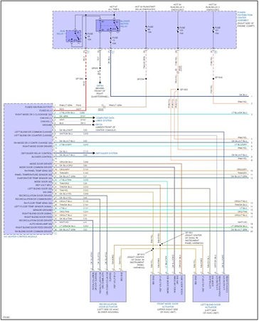 Automotive Wiring Diagram
4. How Do You Use a Multimeter to Test Circuits Based on Wiring Diagrams?
Using a multimeter to test circuits based on wiring diagrams involves setting the multimeter to the correct setting (voltage, resistance, or current), identifying the test points on the diagram, and comparing the measured values to the specifications.
Here’s a step-by-step guide:
- Identify the Circuit: Locate the circuit related to the DTC on the wiring diagram.
- Determine Test Points: Identify the points in the circuit where you need to measure voltage, resistance, or current.
- Set the Multimeter: Select the appropriate setting on the multimeter (DC voltage, resistance, or amperage).
- Connect the Probes: Connect the multimeter probes to the test points. Ensure good contact.
- Take Measurements: Read the value displayed on the multimeter.
- Compare to Specifications: Compare the measured value to the manufacturer’s specifications.
- Analyze the Results: If the measured value is outside the specified range, there is likely a problem in the circuit.
For example, if a wiring diagram specifies a voltage of 12V at a particular point and the multimeter reads 0V, there may be a break in the circuit or a blown fuse. If the diagram indicates a certain resistance and the multimeter reads infinite resistance, there is likely an open circuit.
According to Fluke Corporation, a leading manufacturer of multimeters, understanding how to use a multimeter in conjunction with wiring diagrams is a fundamental skill for automotive technicians.
5. What Are Common Mistakes to Avoid When Using Wiring Diagrams?
Common mistakes to avoid when using wiring diagrams include misinterpreting symbols, neglecting ground connections, and failing to verify wire colors or pin numbers. Ensure that you are using the correct diagram for the specific vehicle make, model, and year.
Here are some common pitfalls to watch out for:
- Using the Wrong Diagram: Always verify that you are using the correct wiring diagram for the specific vehicle make, model, and year.
- Misinterpreting Symbols: Take the time to learn and understand the symbols used in the diagram.
- Neglecting Ground Connections: Poor ground connections are a common cause of electrical problems. Always check the integrity of ground connections.
- Failing to Verify Wire Colors: Wire colors can vary, even within the same vehicle model. Always double-check wire colors to ensure you are testing the correct circuit.
- Ignoring Pin Numbers: Pay attention to pin numbers on connectors. Testing the wrong pin can lead to misdiagnosis.
- Not Checking for Updates: Wiring diagrams can be updated by the manufacturer. Make sure you are using the most current version.
According to Mitchell 1, a leading provider of automotive repair information, avoiding these mistakes can significantly improve diagnostic accuracy and efficiency.
6. How Can You Effectively Trace a Short Circuit Using Wiring Diagrams?
Effectively tracing a short circuit using wiring diagrams involves identifying the affected circuit, disconnecting components, and using a multimeter to locate the short. Start by identifying the circuit associated with the DTC.
Follow these steps:
- Identify the Affected Circuit: Use the wiring diagram to identify the circuit related to the DTC.
- Disconnect Components: Disconnect components in the circuit one at a time to isolate the short.
- Use a Multimeter: Set the multimeter to measure resistance. Connect one probe to ground and the other to the circuit wire.
- Locate the Short: If the multimeter reads low resistance (close to zero), there is a short to ground.
- Isolate the Section: By disconnecting components and testing the resistance, you can isolate the section of the circuit where the short is located.
- Inspect the Wiring: Once you have isolated the section, visually inspect the wiring for damage or chafing.
- Repair the Short: Repair or replace the damaged wiring or component causing the short.
For example, if a fuse keeps blowing, it could indicate a short circuit. By disconnecting components and testing the resistance, you can pinpoint the location of the short and repair it.
According to a training manual from Delphi Technologies, a leading automotive parts manufacturer, this systematic approach is crucial for efficiently tracing and resolving short circuits.
 Automotive Electrical Troubleshooting
7. What Are the Best Practices for Diagnosing Open Circuits With Wiring Diagrams?
The best practices for diagnosing open circuits with wiring diagrams include using the diagram to identify the circuit path, checking for voltage at various points, and testing for continuity. Use a multimeter to test for continuity along the circuit.
Follow these steps:
- Identify the Circuit Path: Use the wiring diagram to trace the circuit from the power source to the component.
- Check for Voltage: Use a multimeter to check for voltage at various points along the circuit. If there is no voltage at a certain point, the open circuit is located somewhere between that point and the power source.
- Test for Continuity: Disconnect the power source and use a multimeter to test for continuity along the circuit. If there is no continuity, there is an open circuit somewhere along that path.
- Inspect Connectors and Wiring: Visually inspect connectors and wiring for damage or corrosion.
- Repair or Replace: Repair or replace any damaged wiring or connectors.
For example, if a light is not working, use the wiring diagram to trace the circuit from the battery to the light. Check for voltage at the light socket. If there is no voltage, test for continuity along the circuit to identify the location of the open circuit.
According to Standard Motor Products, a leading supplier of automotive components, understanding how to diagnose open circuits is essential for resolving many electrical issues.
8. How Do You Diagnose CAN Bus Communication Problems Using Wiring Diagrams?
Diagnosing Controller Area Network (CAN) bus communication problems using wiring diagrams involves checking the physical integrity of the CAN bus wires, verifying proper termination resistance, and using a scan tool to monitor CAN bus data. CAN bus issues can cause a range of symptoms.
Here’s a step-by-step guide:
- Check Physical Integrity: Inspect the CAN bus wires for damage, corrosion, or loose connections.
- Verify Termination Resistance: The CAN bus should have a termination resistor at each end, typically 120 ohms. Use a multimeter to measure the resistance between the CAN high and CAN low wires.
- Use a Scan Tool: Use a scan tool to monitor CAN bus data. Look for error messages or missing data from certain modules.
- Consult Wiring Diagrams: Use wiring diagrams to identify the location of CAN bus wires and termination resistors.
- Check Power and Ground: Verify that all modules connected to the CAN bus have proper power and ground connections.
- Isolate the Fault: Disconnect modules one at a time to see if the CAN bus communication improves.
For example, if a vehicle has multiple warning lights illuminated and a scan tool shows a “no communication” error with several modules, it could indicate a CAN bus problem.
According to Bosch, a leading supplier of automotive electronics, understanding CAN bus communication is essential for diagnosing complex electrical issues in modern vehicles.
9. What Are the Key Differences Between Wiring Diagrams for Different Vehicle Makes and Models?
The key differences between wiring diagrams for different vehicle makes and models include variations in component placement, wire colors, connector types, and system architecture. Each manufacturer has its own conventions and symbols.
Here are some key differences to consider:
- Component Placement: The physical location of components can vary significantly between makes and models.
- Wire Colors: Wire colors may differ, even for the same function.
- Connector Types: Connector designs and pin configurations can vary.
- System Architecture: The overall electrical system design can be different, especially with advanced features like hybrid or electric powertrains.
- Symbols and Abbreviations: Manufacturers may use different symbols and abbreviations in their wiring diagrams.
- Diagram Layout: The layout and organization of the diagram can vary.
It’s crucial to use the correct wiring diagram for the specific vehicle you are working on. Accessing manufacturer-specific repair information is often the best way to ensure accuracy.
According to ALLDATA, a leading provider of automotive repair information, using the correct wiring diagram is essential for accurate diagnosis and repair.
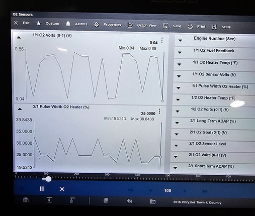 Automotive Scan Tool
10. How Do You Stay Updated With the Latest Wiring Diagram Information and Changes?
Staying updated with the latest wiring diagram information and changes involves subscribing to automotive repair information services, attending training courses, and regularly checking manufacturer websites for updates. Continuous learning is crucial in this field.
Here are some ways to stay current:
- Subscribe to Repair Information Services: Companies like ALLDATA, Mitchell 1, and Identifix provide access to updated wiring diagrams and repair information.
- Attend Training Courses: Participate in training courses offered by automotive manufacturers, technical schools, and industry organizations.
- Check Manufacturer Websites: Regularly check manufacturer websites for technical service bulletins (TSBs) and updated wiring diagrams.
- Join Online Forums: Participate in online forums and communities to share information and learn from other technicians.
- Use Cloud-Based Software: Cloud-based diagnostic software often includes automatic updates to wiring diagrams and repair information.
According to ASE, continuous education and staying informed about the latest technologies are essential for automotive technicians to provide high-quality service.
Wiring diagrams are not just lines on paper; they are the language of your vehicle’s electrical system. By mastering this language, you unlock the ability to diagnose and resolve complex issues with confidence.
Are you ready to elevate your diagnostic skills and become an electrical system expert?
Contact MERCEDES-DIAGNOSTIC-TOOL.EDU.VN today at 789 Oak Avenue, Miami, FL 33101, United States or Whatsapp +1 (641) 206-8880.
Let us equip you with the knowledge and tools you need to conquer any electrical challenge. Visit our website at MERCEDES-DIAGNOSTIC-TOOL.EDU.VN and take the first step towards automotive mastery.
FAQ
- What is a wiring diagram?A wiring diagram is a visual representation of an electrical circuit, showing components and their connections.
- Why are wiring diagrams important for DTC diagnosis?They help trace circuits, identify components, and pinpoint the root cause of electrical issues.
- What tools are needed to effectively use wiring diagrams?A digital multimeter, test light, wire strippers, crimpers, and a wiring diagram database.
- How do I test a circuit using a wiring diagram and a multimeter?Identify test points, set the multimeter to the correct setting, connect the probes, and compare the measured values to specifications.
- What are common mistakes to avoid when using wiring diagrams?Misinterpreting symbols, neglecting ground connections, and failing to verify wire colors or pin numbers.
- How can I trace a short circuit with a wiring diagram?Identify the affected circuit, disconnect components, and use a multimeter to locate the short.
- What’s the best way to diagnose open circuits using wiring diagrams?Identify the circuit path, check for voltage, and test for continuity.
- How do I diagnose CAN bus communication problems with wiring diagrams?Check the physical integrity of the CAN bus wires, verify termination resistance, and use a scan tool to monitor CAN bus data.
- How do wiring diagrams differ between vehicle makes and models?Variations in component placement, wire colors, connector types, and system architecture.
- How can I stay updated with the latest wiring diagram information?Subscribe to repair information services, attend training courses, and regularly check manufacturer websites for updates.