Advanced CAN bus diagnostics, particularly when dealing with U-codes, require specialized tools to effectively troubleshoot and resolve communication issues within a Mercedes-Benz vehicle. MERCEDES-DIAGNOSTIC-TOOL.EDU.VN offers comprehensive solutions, including state-of-the-art diagnostic equipment and expert guidance, to help you navigate the complexities of CAN bus systems. Utilizing the right tools ensures accurate diagnosis and efficient repair, ultimately saving time and resources. This article will explore the essential tools, diagnostic strategies, and how MERCEDES-DIAGNOSTIC-TOOL.EDU.VN can assist you in mastering advanced automotive diagnostics.
Contents
- 1. Understanding CAN Bus and U-Codes in Mercedes-Benz Vehicles
- 1.1. What is the CAN Bus System?
- 1.2. What are U-Codes?
- 1.3. Why Are Advanced Diagnostics Essential for U-Codes?
- 2. Essential Tools for Advanced CAN Bus Diagnostics
- 2.1. Oscilloscope
- 2.1.1. How Does an Oscilloscope Aid in CAN Bus Diagnostics?
- 2.1.2. Recommended Oscilloscope Features
- 2.2. Advanced Diagnostic Scan Tools
- 2.2.1. Capabilities of Advanced Scan Tools
- 2.2.2. Top Scan Tools for Mercedes-Benz
- 2.3. Specialized CAN Bus Diagnostic Tools
- 2.3.1. Features of Specialized Tools
- 2.3.2. Recommended Specialized Tools
- 2.4. Multimeter
- 2.4.1. How a Multimeter Aids in CAN Bus Diagnostics
- 2.4.2. Key Features for a Multimeter
- 2.5. Wiring Diagrams and Technical Documentation
- 2.5.1. Importance of Wiring Diagrams
- 2.5.2. Reliable Sources for Documentation
- 3. Diagnostic Strategies for U-Codes
- 3.1. Initial Assessment
- 3.1.1. Verifying the U-Code
- 3.1.2. Gathering Information
- 3.2. Visual Inspection
- 3.2.1. Inspecting Wiring and Connectors
- 3.2.2. Inspecting ECUs
- 3.3. CAN Bus Testing
- 3.3.1. Measuring CAN Bus Voltage
- 3.3.2. Checking CAN Bus Resistance
- 3.3.3. Analyzing CAN Bus Signals with an Oscilloscope
- 3.4. ECU Isolation
- 3.4.1. Disconnecting ECUs
- 3.4.2. Replacing ECUs
- 3.5. Wiring and Connector Repair
- 3.5.1. Repairing Wiring
- 3.5.2. Repairing Connectors
- 4. Advanced Diagnostic Techniques
- 4.1. Voltage Drop Testing
- 4.1.1. How to Perform Voltage Drop Testing
- 4.1.2. Interpreting Results
- 4.2. Signal Injection
- 4.2.1. How to Perform Signal Injection
- 4.2.2. Interpreting Results
- 4.3. Network Topology Analysis
- 4.3.1. Creating a Network Topology Map
- 4.3.2. Using the Map for Diagnostics
- 5. Case Studies: Diagnosing U-Codes in Mercedes-Benz Vehicles
- 5.1. Case Study 1: U0100 Code in a 2015 C-Class
- 5.1.1. Diagnostic Steps
- 5.1.2. Resolution
- 5.2. Case Study 2: U0155 Code in a 2018 E-Class
- 5.2.1. Diagnostic Steps
- 5.2.2. Resolution
- 5.3. Case Study 3: U1409 Code in a 2020 S-Class
- 5.3.1. Diagnostic Steps
- 5.3.2. Resolution
- 6. Leveraging MERCEDES-DIAGNOSTIC-TOOL.EDU.VN for Advanced Diagnostics
- 6.1. Diagnostic Tools and Equipment
- 6.1.1. Tool Recommendations
- 6.1.2. Equipment Leasing and Rental
- 6.2. Training and Certification Programs
- 6.2.1. CAN Bus Diagnostics Course
- 6.2.2. Mercedes-Benz Specific Training
- 6.3. Technical Support and Resources
- 6.3.1. Online Forum
- 6.3.2. Technical Articles and Guides
- 6.3.3. Remote Diagnostic Support
- 7. Maintaining a Reliable CAN Bus System
- 7.1. Regular Inspections
- 7.2. Connector Maintenance
- 7.3. Software Updates
- 7.4. Proper Wiring Practices
- 8. FAQ: Advanced CAN Bus Diagnostics Related to U-Codes
- 9. Conclusion: Mastering CAN Bus Diagnostics for Mercedes-Benz Vehicles
1. Understanding CAN Bus and U-Codes in Mercedes-Benz Vehicles
The Controller Area Network (CAN) bus is a robust communication network that allows various electronic control units (ECUs) within a vehicle to communicate with each other without a central host computer. U-codes, in automotive diagnostics, signify network communication faults, indicating issues within the CAN bus system. These codes are crucial for diagnosing problems in Mercedes-Benz vehicles, where numerous ECUs rely on seamless communication.
1.1. What is the CAN Bus System?
The CAN bus system enables microcontrollers and devices to communicate within a vehicle without needing a host computer. According to Bosch, one of the pioneers of CAN technology, “The CAN bus is a serial, asynchronous, multi-master broadcast network that enables ECUs to communicate with each other.” This communication is vital for coordinating various functions, from engine management to safety systems.
1.2. What are U-Codes?
U-codes, or network communication codes, signify that an ECU is experiencing communication problems with other modules on the CAN bus. These codes do not pinpoint a specific faulty component but indicate a disruption in the network. For example, a U0100 code indicates “Lost Communication With ECM/PCM,” meaning the Engine Control Module/Powertrain Control Module is not communicating properly.
1.3. Why Are Advanced Diagnostics Essential for U-Codes?
Advanced diagnostics are essential because U-codes can stem from various issues, such as wiring problems, faulty ECUs, or software glitches. Simple code reading is insufficient; a thorough investigation using specialized tools is necessary to accurately identify the root cause and ensure effective repairs. A study by the Society of Automotive Engineers (SAE) highlighted that effective CAN bus diagnostics significantly reduce repair times and improve overall vehicle reliability.
2. Essential Tools for Advanced CAN Bus Diagnostics
To effectively diagnose U-codes in Mercedes-Benz vehicles, you need a comprehensive toolkit that includes oscilloscopes, advanced scan tools, and specialized CAN bus diagnostic tools. Each tool serves a specific purpose in identifying and resolving communication issues.
2.1. Oscilloscope
An oscilloscope is indispensable for visualizing the electrical signals on the CAN bus. It allows you to see the voltage levels and signal integrity, helping to identify noise, signal drops, or other anomalies that can disrupt communication.
2.1.1. How Does an Oscilloscope Aid in CAN Bus Diagnostics?
An oscilloscope allows you to:
- Visualize CAN Bus Signals: View the high and low voltage states of the CAN bus signals.
- Measure Signal Voltage: Verify that the voltage levels are within the specified range (typically 2.5V with deviations for dominant and recessive states).
- Check Signal Integrity: Identify signal reflections, ringing, or other distortions that can indicate wiring issues.
- Detect Noise: Find excessive noise on the CAN bus, which can interfere with communication.
2.1.2. Recommended Oscilloscope Features
- High Bandwidth: At least 100 MHz bandwidth to accurately capture fast CAN bus signals.
- Multiple Channels: Two or more channels to simultaneously monitor CAN High and CAN Low signals.
- Advanced Triggering: Features like CAN bus triggering to capture specific frames or error conditions.
- Automotive Diagnostics Software: Built-in software that decodes CAN bus signals and displays data in a readable format.
2.2. Advanced Diagnostic Scan Tools
Advanced scan tools go beyond basic code reading and provide in-depth diagnostic capabilities, including access to live data, bidirectional controls, and ECU programming.
2.2.1. Capabilities of Advanced Scan Tools
- Code Reading and Clearing: Read diagnostic trouble codes (DTCs) and clear them after repairs.
- Live Data Streaming: Monitor real-time data from various sensors and ECUs.
- Bidirectional Controls: Activate or deactivate components to test their functionality.
- ECU Programming and Coding: Update or reprogram ECUs to address software issues or install new features.
2.2.2. Top Scan Tools for Mercedes-Benz
- Autel MaxiSys Elite II: Offers comprehensive diagnostics, ECU programming, and advanced functions.
- Launch X431 V+: Provides extensive vehicle coverage, bidirectional controls, and ECU coding capabilities.
- Mercedes-Benz Star Diagnosis System (SDS): The official diagnostic tool for Mercedes-Benz vehicles, offering the most comprehensive access to vehicle systems.
2.3. Specialized CAN Bus Diagnostic Tools
Specialized tools are designed specifically for CAN bus diagnostics, offering advanced features such as network analysis, fault localization, and bus simulation.
2.3.1. Features of Specialized Tools
- CAN Bus Analyzers: Capture and analyze CAN bus traffic to identify communication patterns, errors, and bottlenecks.
- Fault Simulators: Simulate faults on the CAN bus to test the response of ECUs and diagnose intermittent issues.
- Breakout Boxes: Provide access to individual pins on the CAN bus for testing and measurement.
2.3.2. Recommended Specialized Tools
- CAN Bus Tester 1100: A portable CAN bus analyzer that displays bus load, error frames, and data traffic.
- Kvaser Leaf Light v2: A reliable CAN bus interface for connecting to a vehicle’s CAN bus and analyzing network data.
- Vector Informatik CANoe: A comprehensive tool for simulating, testing, and analyzing CAN bus systems.
2.4. Multimeter
A multimeter is a fundamental tool for measuring voltage, current, and resistance in electrical circuits, essential for verifying the integrity of wiring and connections.
2.4.1. How a Multimeter Aids in CAN Bus Diagnostics
- Voltage Measurements: Verify the voltage levels at various points on the CAN bus.
- Continuity Testing: Check for open circuits or shorts in the wiring.
- Resistance Measurements: Measure the resistance of CAN bus terminators to ensure they are within the specified range (typically 120 ohms).
2.4.2. Key Features for a Multimeter
- Accuracy: High accuracy for precise measurements.
- Auto-Ranging: Automatically selects the appropriate measurement range.
- Continuity Tester: Audible beep to indicate continuity in a circuit.
2.5. Wiring Diagrams and Technical Documentation
Having access to accurate wiring diagrams and technical documentation is crucial for understanding the CAN bus network and identifying the correct testing points.
2.5.1. Importance of Wiring Diagrams
- Locating Components: Identify the location of ECUs, connectors, and wiring harnesses.
- Understanding Circuit Paths: Trace the flow of signals through the CAN bus network.
- Identifying Test Points: Determine the best points for measuring voltage, resistance, and signal integrity.
2.5.2. Reliable Sources for Documentation
- Mercedes-Benz WIS (Workshop Information System): The official source for Mercedes-Benz repair information.
- AllData: A comprehensive database of automotive repair information.
- Mitchell OnDemand: Provides wiring diagrams, technical service bulletins, and repair procedures.
3. Diagnostic Strategies for U-Codes
Diagnosing U-codes requires a systematic approach to identify the root cause of the communication issue. Following a structured diagnostic strategy ensures thoroughness and accuracy.
3.1. Initial Assessment
Begin by verifying the U-code and gathering preliminary information about the vehicle’s symptoms and recent repairs.
3.1.1. Verifying the U-Code
Use a scan tool to confirm the presence of the U-code and note any other related DTCs.
3.1.2. Gathering Information
- Vehicle History: Review the vehicle’s maintenance and repair history for any relevant information.
- Symptoms: Note any drivability issues, warning lights, or other symptoms the vehicle is exhibiting.
- Recent Repairs: Inquire about any recent repairs or modifications that may have affected the CAN bus network.
3.2. Visual Inspection
Perform a thorough visual inspection of the wiring, connectors, and ECUs to identify any obvious signs of damage or corrosion.
3.2.1. Inspecting Wiring and Connectors
- Check for Damage: Look for frayed, cracked, or damaged wiring.
- Examine Connectors: Ensure connectors are securely connected and free from corrosion.
- Inspect Grounds: Verify that ground connections are clean and tight.
3.2.2. Inspecting ECUs
- Check for Physical Damage: Look for signs of physical damage to the ECU housings.
- Examine Connectors: Ensure ECU connectors are properly seated and free from corrosion.
3.3. CAN Bus Testing
Use an oscilloscope and multimeter to test the CAN bus signals and verify the integrity of the network.
3.3.1. Measuring CAN Bus Voltage
- Key Off: Measure the voltage between CAN High and CAN Low with the ignition off. The voltage should be close to 0V.
- Key On: Measure the voltage with the ignition on. CAN High should be around 2.5V to 3.5V, and CAN Low should be around 1.5V to 2.5V.
3.3.2. Checking CAN Bus Resistance
- Key Off: Disconnect the battery and measure the resistance between CAN High and CAN Low at the DLC (Data Link Connector). The resistance should be approximately 60 ohms if the terminators are functioning correctly.
- High Resistance: If the resistance is higher than 60 ohms, check the terminator resistors at each end of the CAN bus.
3.3.3. Analyzing CAN Bus Signals with an Oscilloscope
- Connect Oscilloscope: Connect the oscilloscope probes to CAN High and CAN Low at the DLC.
- Capture Waveforms: Capture the CAN bus waveforms while the vehicle is running.
- Analyze Signals: Look for signal abnormalities such as noise, reflections, or missing data.
3.4. ECU Isolation
If the CAN bus tests reveal a problem with a specific ECU, isolate the ECU to determine if it is causing the communication issue.
3.4.1. Disconnecting ECUs
- Isolate Suspect ECU: Disconnect the suspect ECU from the CAN bus.
- Retest CAN Bus: Retest the CAN bus signals to see if the problem is resolved.
3.4.2. Replacing ECUs
- Replace Faulty ECU: If the CAN bus signals return to normal after disconnecting the ECU, replace the faulty ECU.
- Program ECU: Program the new ECU to match the vehicle’s configuration.
3.5. Wiring and Connector Repair
Repair any damaged wiring or connectors to restore proper communication on the CAN bus.
3.5.1. Repairing Wiring
- Solder Connections: Solder any broken wires and insulate them with heat-shrink tubing.
- Replace Damaged Sections: Replace sections of wiring that are severely damaged.
3.5.2. Repairing Connectors
- Clean Corrosion: Clean any corrosion from connector pins using a contact cleaner.
- Replace Damaged Connectors: Replace connectors that are cracked or damaged.
4. Advanced Diagnostic Techniques
Mastering advanced diagnostic techniques can significantly improve your ability to diagnose and resolve complex CAN bus issues.
4.1. Voltage Drop Testing
Voltage drop testing involves measuring the voltage drop across a circuit to identify areas of high resistance. This technique is particularly useful for locating corroded connections or damaged wiring.
4.1.1. How to Perform Voltage Drop Testing
- Connect Multimeter: Connect the multimeter leads to both ends of the circuit you want to test.
- Apply Load: Apply a load to the circuit by turning on the component.
- Measure Voltage Drop: Measure the voltage drop across the circuit. A high voltage drop indicates high resistance.
4.1.2. Interpreting Results
- Low Voltage Drop: A low voltage drop (less than 0.2V) indicates a good connection.
- High Voltage Drop: A high voltage drop (more than 0.5V) indicates a poor connection or damaged wiring.
4.2. Signal Injection
Signal injection involves injecting a test signal into the CAN bus to verify the integrity of the wiring and ECUs. This technique can help identify breaks in the wiring or faulty ECUs that are not responding to the signal.
4.2.1. How to Perform Signal Injection
- Disconnect ECU: Disconnect the ECU from the CAN bus.
- Inject Signal: Inject a test signal into the CAN bus using a signal generator.
- Measure Signal: Measure the signal at various points along the CAN bus to verify its presence and integrity.
4.2.2. Interpreting Results
- Signal Present: If the signal is present at all test points, the wiring is intact.
- Signal Absent: If the signal is absent at a test point, there is a break in the wiring between the signal generator and the test point.
4.3. Network Topology Analysis
Network topology analysis involves mapping the CAN bus network to understand the relationships between ECUs and identify potential points of failure.
4.3.1. Creating a Network Topology Map
- Identify ECUs: Identify all the ECUs on the CAN bus network.
- Trace Connections: Trace the wiring connections between the ECUs.
- Create Map: Create a map of the CAN bus network showing the location of ECUs and the connections between them.
4.3.2. Using the Map for Diagnostics
- Identify Potential Issues: Use the map to identify potential points of failure based on the location of ECUs and the connections between them.
- Isolate Faults: Use the map to isolate faults by disconnecting ECUs and testing the CAN bus signals.
5. Case Studies: Diagnosing U-Codes in Mercedes-Benz Vehicles
Examining real-world case studies can provide valuable insights into diagnosing U-codes in Mercedes-Benz vehicles.
5.1. Case Study 1: U0100 Code in a 2015 C-Class
A 2015 Mercedes-Benz C-Class exhibited a U0100 code (“Lost Communication With ECM/PCM”) along with drivability issues.
5.1.1. Diagnostic Steps
- Initial Assessment: Verified the U0100 code and noted the drivability issues.
- Visual Inspection: Found a corroded connector at the ECM.
- CAN Bus Testing: Measured abnormal voltage levels on the CAN bus.
- Connector Repair: Cleaned the corroded connector and retested the CAN bus.
5.1.2. Resolution
Cleaning the corroded connector restored proper communication, resolving the U0100 code and drivability issues.
5.2. Case Study 2: U0155 Code in a 2018 E-Class
A 2018 Mercedes-Benz E-Class displayed a U0155 code (“Lost Communication With Instrument Panel Cluster”).
5.2.1. Diagnostic Steps
- Initial Assessment: Verified the U0155 code and noted the instrument panel was not functioning correctly.
- Visual Inspection: Found no obvious damage to wiring or connectors.
- CAN Bus Testing: Analyzed CAN bus signals with an oscilloscope and identified signal distortions.
- ECU Isolation: Disconnected the instrument panel cluster and retested the CAN bus.
5.2.2. Resolution
Disconnecting the instrument panel cluster restored normal CAN bus signals. The instrument panel cluster was replaced and programmed, resolving the U0155 code.
5.3. Case Study 3: U1409 Code in a 2020 S-Class
A 2020 Mercedes-Benz S-Class presented a U1409 code (“Implausible Signal Received From Steering Column Module”).
5.3.1. Diagnostic Steps
- Initial Assessment: Verified the U1409 code and noted issues with the steering column functions.
- Visual Inspection: Inspected the wiring and connectors at the steering column module.
- CAN Bus Testing: Used a CAN bus analyzer to monitor communication between the steering column module and other ECUs.
- Signal Injection: Injected a test signal into the CAN bus to verify the integrity of the wiring.
5.3.2. Resolution
Signal injection revealed a break in the wiring between the steering column module and the CAN bus. The wiring was repaired, resolving the U1409 code and restoring normal steering column functions.
6. Leveraging MERCEDES-DIAGNOSTIC-TOOL.EDU.VN for Advanced Diagnostics
MERCEDES-DIAGNOSTIC-TOOL.EDU.VN offers a range of resources to help you master advanced CAN bus diagnostics and effectively resolve U-codes in Mercedes-Benz vehicles.
6.1. Diagnostic Tools and Equipment
MERCEDES-DIAGNOSTIC-TOOL.EDU.VN provides access to state-of-the-art diagnostic tools and equipment, including oscilloscopes, advanced scan tools, and specialized CAN bus diagnostic tools.
6.1.1. Tool Recommendations
- Autel MaxiSys Elite II: For comprehensive diagnostics and ECU programming.
- CAN Bus Tester 1100: For portable CAN bus analysis.
- Fluke 88V Multimeter: For accurate voltage, current, and resistance measurements.
6.1.2. Equipment Leasing and Rental
MERCEDES-DIAGNOSTIC-TOOL.EDU.VN offers equipment leasing and rental options to provide access to diagnostic tools without the upfront cost of purchasing.
6.2. Training and Certification Programs
MERCEDES-DIAGNOSTIC-TOOL.EDU.VN offers training and certification programs to enhance your diagnostic skills and knowledge.
6.2.1. CAN Bus Diagnostics Course
A comprehensive course covering the fundamentals of CAN bus systems, diagnostic strategies, and advanced diagnostic techniques.
6.2.2. Mercedes-Benz Specific Training
Training programs tailored to Mercedes-Benz vehicles, covering specific diagnostic procedures and repair techniques.
6.3. Technical Support and Resources
MERCEDES-DIAGNOSTIC-TOOL.EDU.VN provides technical support and resources to assist you with your diagnostic challenges.
6.3.1. Online Forum
A forum where you can ask questions, share experiences, and get advice from other technicians.
6.3.2. Technical Articles and Guides
A library of technical articles and guides covering various diagnostic topics.
6.3.3. Remote Diagnostic Support
Remote diagnostic support services to assist you with complex diagnostic issues.
7. Maintaining a Reliable CAN Bus System
Preventive maintenance is essential for ensuring the reliability of the CAN bus system and avoiding U-codes.
7.1. Regular Inspections
Perform regular visual inspections of the wiring, connectors, and ECUs to identify any potential problems.
7.2. Connector Maintenance
Clean and lubricate connectors to prevent corrosion and ensure proper connectivity.
7.3. Software Updates
Keep the ECU software up to date to address any known issues and improve performance.
7.4. Proper Wiring Practices
Follow proper wiring practices when installing aftermarket components to avoid disrupting the CAN bus network.
8. FAQ: Advanced CAN Bus Diagnostics Related to U-Codes
8.1. What is the first step in diagnosing a U-code?
The first step is to verify the U-code with a scan tool and gather information about the vehicle’s symptoms and recent repairs to provide context.
8.2. Why is an oscilloscope important for CAN bus diagnostics?
An oscilloscope allows you to visualize the electrical signals on the CAN bus, helping identify noise, signal drops, or other anomalies.
8.3. How do I check CAN bus resistance?
Disconnect the battery and measure the resistance between CAN High and CAN Low at the DLC. The resistance should be approximately 60 ohms.
8.4. What does a high voltage drop indicate in voltage drop testing?
A high voltage drop indicates high resistance, which can be due to a poor connection or damaged wiring.
8.5. Can aftermarket components cause U-codes?
Yes, improper installation of aftermarket components can disrupt the CAN bus network and cause U-codes.
8.6. What is ECU isolation, and why is it important?
ECU isolation involves disconnecting ECUs to determine if a specific ECU is causing the communication issue, helping to pinpoint faulty components.
8.7. How often should I inspect the CAN bus system?
Regular visual inspections should be performed during routine maintenance to identify potential problems early.
8.8. What are the key features of an advanced diagnostic scan tool?
Key features include code reading and clearing, live data streaming, bidirectional controls, and ECU programming.
8.9. What is signal injection, and how does it help in diagnostics?
Signal injection involves injecting a test signal into the CAN bus to verify the integrity of the wiring and ECUs, helping to identify breaks in the wiring or faulty ECUs.
8.10. Where can I find reliable wiring diagrams for Mercedes-Benz vehicles?
Reliable sources include Mercedes-Benz WIS (Workshop Information System), AllData, and Mitchell OnDemand.
9. Conclusion: Mastering CAN Bus Diagnostics for Mercedes-Benz Vehicles
Advanced CAN bus diagnostics is crucial for effectively resolving U-codes and ensuring the reliable operation of Mercedes-Benz vehicles. By utilizing the right tools, following a systematic diagnostic strategy, and leveraging the resources available at MERCEDES-DIAGNOSTIC-TOOL.EDU.VN, you can master the complexities of CAN bus systems and deliver top-notch diagnostic and repair services. Remember, accurate diagnosis and efficient repair not only save time and resources but also enhance customer satisfaction and build trust in your expertise.
Don’t let complex U-codes slow you down. Contact MERCEDES-DIAGNOSTIC-TOOL.EDU.VN today for expert guidance on selecting the right diagnostic tools, accessing comprehensive training programs, and receiving unparalleled technical support. Visit us at 789 Oak Avenue, Miami, FL 33101, United States, or reach out via Whatsapp at +1 (641) 206-8880. Explore our website at MERCEDES-DIAGNOSTIC-TOOL.EDU.VN to unlock the full potential of your diagnostic capabilities.
 Autel Maxisys Ultra Top Diagnostic Scanner
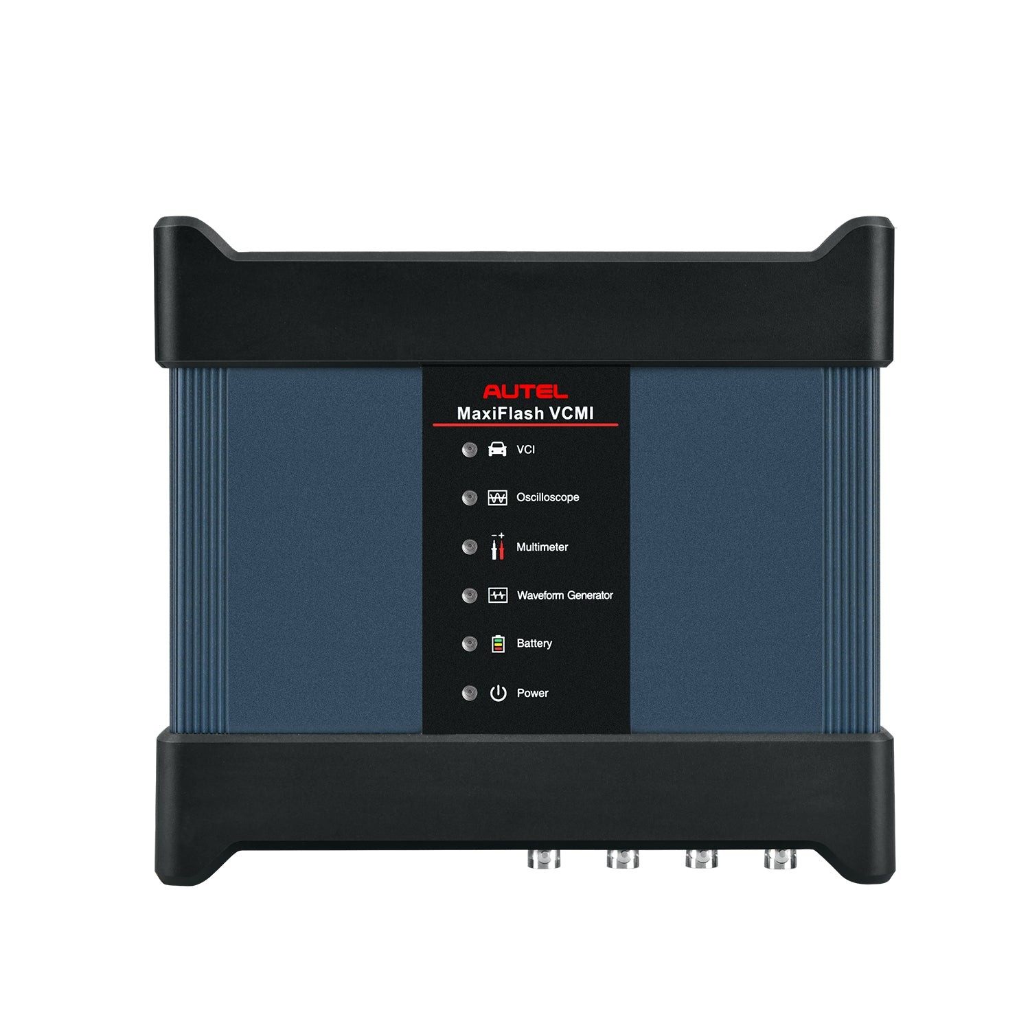 Autel Maxisys Ultra MaxiFlash VCMI
 Autel Maxisys Ultra Docking Station