The Controller Area Network (CAN) bus function in vehicle communication is to enable Electronic Control Units (ECUs) to communicate efficiently without a central host, as explained by MERCEDES-DIAGNOSTIC-TOOL.EDU.VN. This system enhances reliability and reduces wiring complexity, making modern vehicles more responsive and interconnected. Leveraging this understanding can lead to optimized vehicle diagnostics and performance enhancements, with tools like data loggers and interfaces improving overall maintenance and functionality.
Contents
- 1. Understanding the CAN Bus System
- 1.1 The Role of ECUs
- 1.2 Physical Structure of the CAN Bus
- 1.3 ECU Components
- 1.4 Connecting to the CAN Bus
- 1.5 Variants of CAN Bus
- 1.6 Other Network Systems
- 2. Key Benefits of the CAN Bus
- 2.1 Simplicity and Low Cost
- 2.2 Easy Access and Centralized Diagnostics
- 2.3 Robustness
- 2.4 Efficiency
- 3. A Brief History of the CAN Bus
- 4. The Future of CAN Bus Technology
- 5. CAN Physical and Data Link Layers
- 5.1 Physical Layer (ISO 11898-2)
- 5.2 Data Link Layer (ISO 11898-1)
- 6. Understanding CAN Frames
- 6.1 CAN Frame Variants
- 7. Higher-Layer CAN Protocols
- 7.1 Common Automotive/Industrial CAN Protocols
- 7.2 Understanding CAN Bus and Higher-Layer Protocols
- 7.3 Other Common Higher-Layer CAN Protocols
- 8. How to Log CAN Bus Data
- 8.1 Select the Right Hardware
- 8.2 Identify the Adapter Cable
- 8.3 Additional Tips Based on Use Case
- 8.4 Configure and Connect Your Device
- 8.5 Review Your Raw CAN Data
- 9. How to Decode Raw CAN Data
- 9.1 Understand CAN Signal Extraction
- 9.2 Get the Relevant DBC File
- 9.3 Use a Software/API Tool
- 10. CAN Data Logging Use Cases
- 10.1 Logging/Streaming Data from Cars
- 10.2 Heavy-Duty Fleet Telematics
- 10.3 Predictive Maintenance
- 10.4 Vehicle/Machine Black Box
- FAQ: Understanding the CAN Bus in Vehicle Communication
- 1. What is the primary function of the CAN bus in a vehicle?
- 2. How does the CAN bus reduce wiring complexity in vehicles?
- 3. What are the key benefits of using a CAN bus in automotive applications?
- 4. What are the different types of CAN bus variants available?
- 5. What is an ECU, and what role does it play in the CAN bus system?
- 6. How can I connect to a CAN bus for diagnostics or data logging?
- 7. What is a DBC file, and why is it needed for CAN bus data analysis?
- 8. What types of higher-layer protocols are used with the CAN bus?
- 9. Can the CAN bus be used for predictive maintenance in vehicles?
- 10. What is the future of CAN bus technology in the automotive industry?
1. Understanding the CAN Bus System
The Controller Area Network (CAN) bus is a critical communication system in modern vehicles, enabling various electronic components to interact seamlessly. It acts as a central nervous system, facilitating the exchange of information between different parts of the vehicle.
1.1 The Role of ECUs
Electronic Control Units (ECUs), often referred to as ‘CAN nodes,’ are integral components that manage specific functions within a vehicle. These can include the engine control unit, transmission, brakes, steering, and temperature regulation. A modern car can have over 70 ECUs, each contributing to the vehicle’s overall operation by sharing data via the CAN bus.
1.2 Physical Structure of the CAN Bus
Physically, the CAN bus consists of a two-wire system: CAN high and CAN low, typically twisted to minimize electromagnetic interference. These wires connect all ECUs, allowing them to transmit and receive data. The CAN high wire is often yellow, while the CAN low wire is green.
1.3 ECU Components
Each ECU comprises three main elements:
- Microcontroller (MCU): The brain of the ECU, interpreting incoming CAN messages and deciding what messages to transmit.
- CAN Controller: Integrated in the MCU, ensuring all communication adheres to the CAN protocol.
- CAN Transceiver: Connects the CAN controller to the physical CAN wires, converting data into differential signals and providing electrical protection.
1.4 Connecting to the CAN Bus
Connecting to a CAN bus requires a connector, though there is no universal standard. The CAN DB9 (D-sub9) connector is a common choice for data loggers and interfaces.
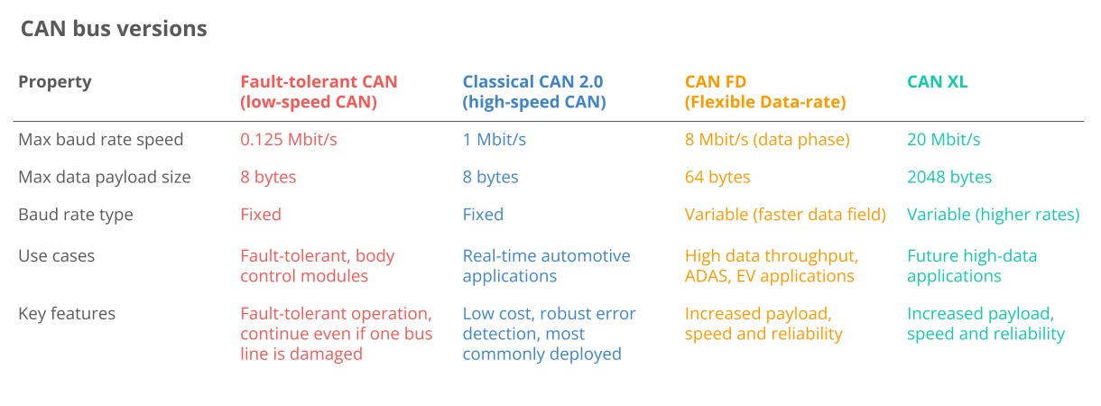
1.5 Variants of CAN Bus
Multiple CAN bus variants exist, each suited for different applications:
- Low-speed CAN: Used when fault tolerance is critical but increasingly replaced by LIN bus.
- High-speed CAN: The most common variant in automotive and machinery.
- CAN FD: Offers longer payloads and faster speeds.
- CAN XL: Provides even longer payloads and faster speeds, bridging the gap between CAN and Automotive Ethernet.
 Classical CAN FD XL Variants canbus
1.6 Other Network Systems
In addition to CAN, other network systems are used in vehicles:
- LIN Bus: A lower-cost supplement to CAN, used for non-critical functions.
- FlexRay: Offers higher speed and fault tolerance but is more costly.
- Automotive Ethernet: Supports high bandwidth requirements for ADAS and infotainment systems.
2. Key Benefits of the CAN Bus
The CAN bus standard is widely used in vehicles and machines due to its numerous advantages.
2.1 Simplicity and Low Cost
ECUs communicate via a single CAN system instead of complex analog signal lines, reducing errors, weight, wiring, and costs.
- Reduced Wire Complexity: Traditional wiring systems require dedicated wires between each node, increasing costs and reducing flexibility.
- Weight Reduction: CAN bus can reduce the weight of a vehicle’s wiring harness by up to 20 kg, improving fuel efficiency.
- Scale: The widespread use of CAN reduces the cost of controllers, transceivers, and data acquisition hardware.
2.2 Easy Access and Centralized Diagnostics
The CAN bus provides a single point of entry for communicating with all network ECUs, enabling central diagnostics, data logging, and configuration.
- Centralized Diagnostics: Direct access to all traffic simplifies diagnostics, eliminating the need to collect data individually for each node.
- Silent CAN Logging: CAN bus data logging can be performed in silent mode, ensuring the device does not affect the CAN bus.
- ECU Flashing: Firmware and configuration updates can be transmitted to any ECU on the network via CAN frames.
- Standardization: Standardized higher-layer protocols enhance the interoperability of hardware and software tools.
2.3 Robustness
The system is robust to electrical disturbances and electromagnetic interference, making it ideal for safety-critical applications.
- Differential Signaling: Electromagnetic interference affects both lines equally, making the differential signal robust.
- Error Handling: Extensive error detection ensures data integrity, including bit errors, stuff errors, CRC errors, form errors, and ACK errors.
- Confinement: CAN nodes track their own errors and disconnect from the bus if thresholds are exceeded.
2.4 Efficiency
CAN frames are prioritized by ID, allowing high-priority data to gain immediate bus access without interrupting other frames.
- Arbitration: Frames with the lowest CAN ID (highest priority) win when multiple nodes attempt to transmit data, avoiding collisions.
- Utilization: Arbitration helps ensure the CAN bus bandwidth is well-utilized.
- Speed: Classical CAN offers sufficient speed for most automotive and industrial applications, enabling communication of thousands of CAN frames per second.
3. A Brief History of the CAN Bus
The CAN bus has evolved significantly since its inception, becoming a staple in automotive and industrial applications.
- Pre-CAN: Car ECUs relied on complex point-to-point wiring.
- 1986: Bosch developed the CAN protocol.
- 1991: Bosch published CAN 2.0 (CAN 2.0A: 11 bit, 2.0B: 29 bit).
- 1993: CAN is adopted as an international standard (ISO 11898).
- 2003: ISO 11898 becomes a standard series.
- 2012: Bosch released CAN FD 1.0 (flexible data rate).
- 2015: The CAN FD protocol is standardized (ISO 11898-1).
- 2016: The physical CAN layer for data rates up to 5 Mbit/s standardized in ISO 11898-2.
- 2018: CiA starts development of CAN XL.
- 2024: CAN XL standardized (ISO 11898-1:2024, 11898-2:2024).
Today, CAN is standard in automotives, ships, planes, EV batteries, machinery, and more.
4. The Future of CAN Bus Technology
The CAN bus protocol will remain relevant, influenced by major trends.
- Need for Speed: Demand for higher data rates may drive the transition towards CAN FD, CAN XL, or Automotive Ethernet.
- Connected Vehicles: The rise of cloud computing and vehicle telematics may enable predictive maintenance and remote troubleshooting but also cybersecurity risks.
- Open vs Closed: A push towards Open Source and Right to Repair may conflict with OEM demands for proprietary data to offer subscription-based microservices.
5. CAN Physical and Data Link Layers
The controller area network is described by a data link layer and physical layer. For high-speed CAN, ISO 11898-1 describes the data link layer, while ISO 11898-2 describes the physical layer.
5.1 Physical Layer (ISO 11898-2)
The CAN bus physical layer defines cable types, electrical signal levels, node requirements, and cable impedance.
- Baud Rate: Nodes must be connected via a two-wire bus with baud rates up to 1 Mbit/s (Classical CAN) or 8 Mbit/s (CAN FD).
- Cable Length: Maximal CAN cable lengths should be between 500 meters (125 kbit/s) and 40 meters (1 Mbit/s).
- Termination: The CAN bus must be terminated using a 120 Ohm termination resistor at each end of the bus.
5.2 Data Link Layer (ISO 11898-1)
The CAN bus data link layer defines CAN frame formats, error handling, and data transmission.
- Frame Formats: Four types of frames (data frames, remote frames, error frames, overload frames) and 11-bit/29-bit identifiers.
- Error Handling: Methods for detecting and handling CAN errors, including CRC, acknowledgement slots, and error counters.
- Arbitration: Non-destructive bitwise arbitration manages CAN bus access and avoids collisions via ID-based priority.
6. Understanding CAN Frames
Communication over the CAN bus is done via CAN frames, as per the data link layer.
Below is a standard CAN data frame with an 11-bit identifier (CAN 2.0A), commonly used in most cars. The extended 29-bit identifier frame (CAN 2.0B) is identical except for the longer ID. It is used in protocols like J1939 for heavy-duty vehicles.
- SOF (Start of Frame): A ‘dominant 0’ signals the start of a transmission.
- ID (Identifier): The frame identifier, with lower values having higher priority.
- RTR (Remote Transmission Request): Indicates whether a node sends data or requests data.
- Control: Contains the Identifier Extension Bit (IDE) and the Data Length Code (DLC) specifying the length of the data bytes (0 to 8 bytes).
- Data: Contains the data bytes, including CAN signals.
- CRC (Cyclic Redundancy Check): Ensures data integrity.
- ACK (Acknowledge): Indicates if the node has received the data correctly.
- EOF (End of Frame): Marks the end of the CAN frame.
6.1 CAN Frame Variants
Four CAN frame variants exist:
- Data Frame: Carries data from a sender CAN node to one or more receiver nodes.
- Error Frame: Indicates the detection of a communication error.
- Remote Frame: Requests data from a CAN node.
- Overload Frame: Provides additional delay between CAN frames.
7. Higher-Layer CAN Protocols
CAN provides a basis for communication, but higher-layer protocols detail how data is communicated between CAN nodes.
7.1 Common Automotive/Industrial CAN Protocols
- OBD2 (On-Board Diagnostics): Used for diagnostics, maintenance, and emissions tests, specifying diagnostic trouble codes (DTCs) and real-time data.
- UDS (Unified Diagnostic Services): A communication protocol used in automotive ECUs for diagnostics, firmware updates, and routine testing.
- CCP/XCP (CAN Calibration Protocol/Universal Measurement and Calibration Protocol): Enables read/write ECU access for calibration, measurement, and flashing.
- CANopen: Used in embedded control applications, including industrial automation, to enable interoperability between CAN nodes.
- SAE J1939: Used in heavy-duty vehicles, identifying parameters like speed with suspect parameter numbers (SPN).
- NMEA 2000: Used in the maritime industry for connecting engines, instruments, and sensors on boats.
- ISOBUS: Used in agriculture and forestry machinery, enabling plug & play integration between vehicles and implements.
7.2 Understanding CAN Bus and Higher-Layer Protocols
CAN bus defines the physical requirements, while higher-layer protocols reflect different languages. In practical applications, a higher-layer protocol is always in use, providing meaningful context to the data.
- Thousands of Protocols: Many more protocols exist, including manufacturer-specific ones.
- Recording vs Understanding Data: A CAN bus data logger can record any CAN-based communication, but understanding the language (i.e., the higher-layer protocol) is essential to interpret the data.
- Multiple Protocols: Cars may use a car-specific CAN protocol and standardized protocols like OBD2 or UDS on the same CAN bus.
- Interoperability: Standardized higher-layer protocols provide interoperability across applications.
7.3 Other Common Higher-Layer CAN Protocols
- ARINC: Commonly used in the aerospace industry.
- UAVCAN: Open source and lightweight protocol often used in drones and robotics.
- DeviceNet: Used in industrial automation and manufacturing.
- SafetyBUS p: Used in safety-critical industrial automation use cases.
- MilCAN: Designed for use in military vehicles and harsh environments.
- HVAC CAN: Designed for use in Heating, Ventilation, and Air Conditioning (HVAC) systems.
8. How to Log CAN Bus Data
Logging CAN bus data involves several critical steps.
8.1 Select the Right Hardware
Decide how you wish to collect the CAN data.
8.2 Identify the Adapter Cable
Determine the appropriate adapter for your application.
- OBD2 Adapter: Used in most cars for OBD2/UDS data and access to the car’s proprietary CAN data.
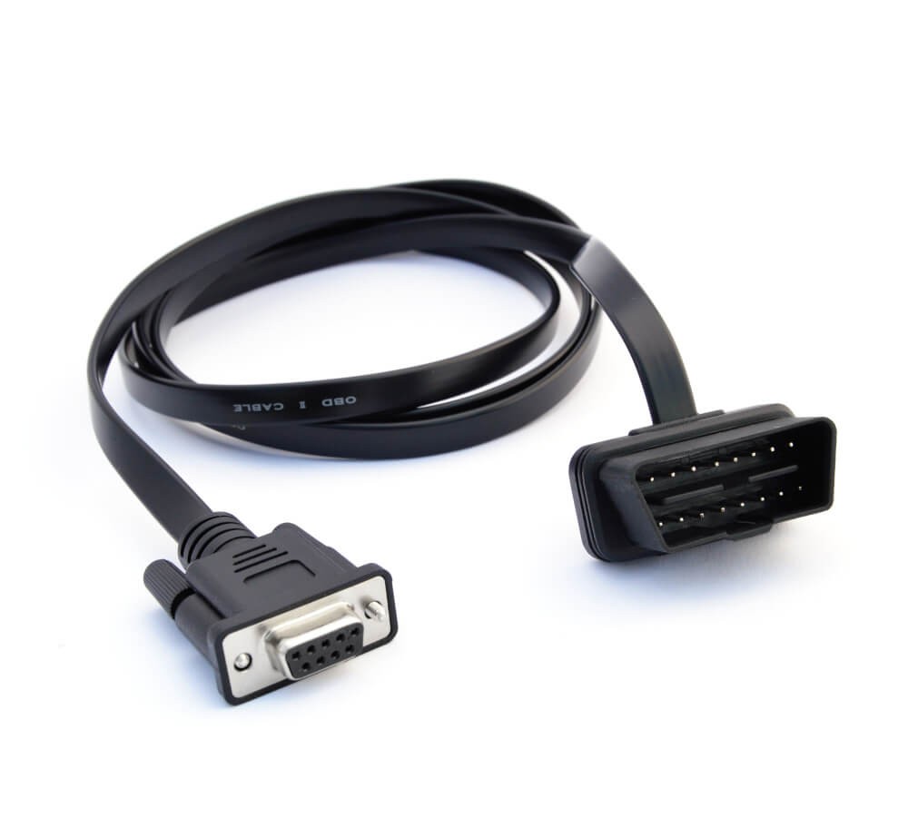 On Board Diagnostic OBD2 Connector Adapter
- J1939 Adapter: Used in most heavy-duty vehicles for raw CAN data (J1939 protocol).
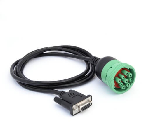 J1939 Deutsch Connector Adapter Cable
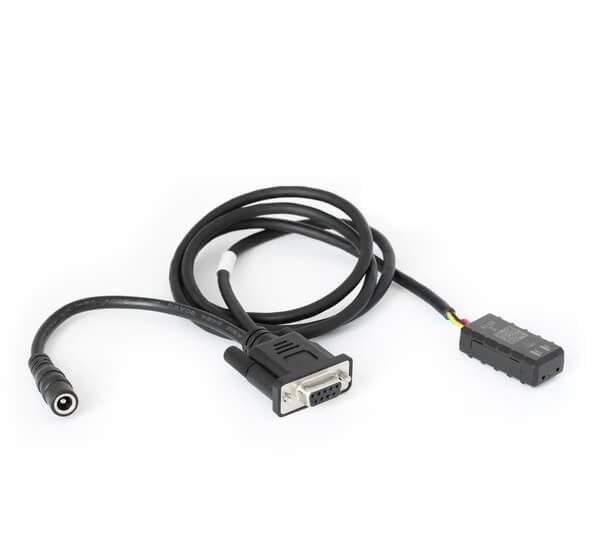
- M12 Adapter: Used in maritime vessels and some industrial machinery for raw CAN data (NMEA 2000 or CANopen).
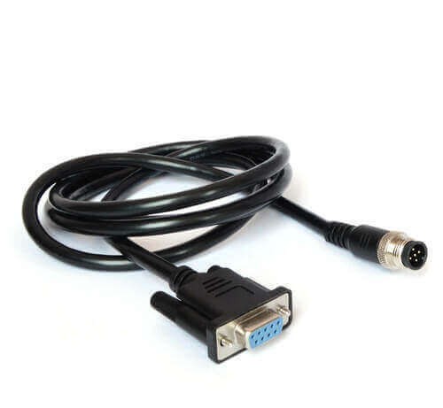 M12 DB9 5-pin cable
- Contactless Reader: A universal option to read data from the CAN high/low wiring harness directly.
 Contactless CAN reader
8.3 Additional Tips Based on Use Case
- Cars: An OBD2 adapter is typically needed, but a contactless CAN reader may be necessary for proprietary data.
- Heavy-Duty: A J1939 adapter is common, but other connectors may be used.
- Maritime: An M12 connector is most often used.
- Industrial Machinery: An M12 adapter is often used.
- Agriculture: A J1939 adapter can be used to record J1939 data.
- Labs & Test Benches: A generic adapter can provide open-wire connections.
- Universal: A contactless CAN reader can always be used.
8.4 Configure and Connect Your Device
Before connecting, ensure your device’s baud rate matches the CAN bus. If you aim to record on-request data like OBD2/UDS, configure your device to transmit the relevant request messages.
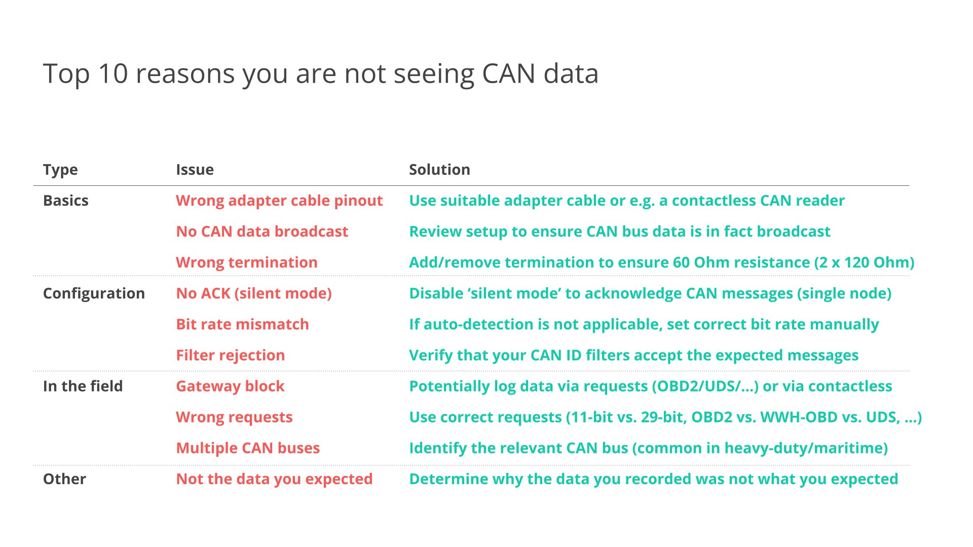 Top 10 CAN logging issues
8.5 Review Your Raw CAN Data
Review the resulting log file after recording. The data will be in a tabular structure, with each line reflecting a timestamped CAN frame including a CAN ID and data payload.
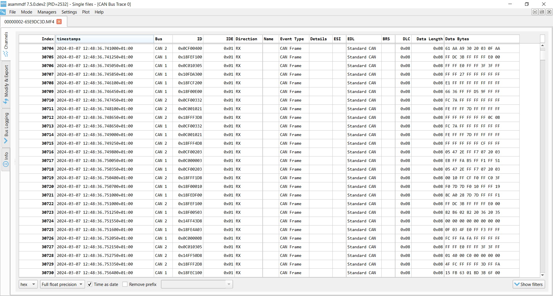 Raw CAN bus data example asammdf J1939
9. How to Decode Raw CAN Data
Raw CAN bus data is not human-readable and needs to be decoded into scaled engineering values.
9.1 Understand CAN Signal Extraction
Each CAN frame contains CAN signals in the data payload. To extract the physical value of a CAN signal, information such as byte order, bit start, bit length, offset, and scale is required.
9.2 Get the Relevant DBC File
A CAN DBC file (CAN database) is a text file containing information for decoding raw CAN data. DBC files are typically application-specific and proprietary, available only to the Original Equipment Manufacturer (OEM).
- OEM Engineer: If you are an OEM engineer, you will typically have the DBC file or the information to create one.
- Non-OEM: Consider standard DBC files for protocols like J1939, NMEA 2000, ISOBUS, or OBD2.
9.3 Use a Software/API Tool
Use a software/API tool that supports your log file format and DBC files. Examples include asammdf GUI, Grafana dashboards, MATLAB, and Python.
10. CAN Data Logging Use Cases
There are several common use cases for recording CAN bus data.
10.1 Logging/Streaming Data from Cars
OBD2 data from cars can be used to reduce fuel costs, improve driving, test prototype parts, and for insurance purposes.
10.2 Heavy-Duty Fleet Telematics
J1939 data from trucks, buses, tractors, etc., can be used in fleet management to reduce costs or improve safety.
10.3 Predictive Maintenance
Vehicles and machinery can be monitored via IoT CAN loggers in the cloud to predict and avoid breakdowns.
10.4 Vehicle/Machine Black Box
A CAN logger can serve as a ‘black box’ for vehicles or equipment, providing data for disputes or diagnostics.
FAQ: Understanding the CAN Bus in Vehicle Communication
1. What is the primary function of the CAN bus in a vehicle?
The CAN bus’s primary function is to allow various ECUs within a vehicle to communicate with each other without needing a central computer, facilitating efficient data sharing and control.
2. How does the CAN bus reduce wiring complexity in vehicles?
By using a single CAN bus system, ECUs can communicate via a shared network rather than direct, complex wiring, which reduces the amount of wiring needed and lowers the risk of errors.
3. What are the key benefits of using a CAN bus in automotive applications?
Key benefits include reduced wiring complexity, lower weight, cost efficiency, easy access for diagnostics, robustness against electrical disturbances, and efficient data prioritization.
4. What are the different types of CAN bus variants available?
The variants include Low-speed CAN, High-speed CAN, CAN FD, and CAN XL, each designed for specific applications and data transfer needs.
5. What is an ECU, and what role does it play in the CAN bus system?
An ECU (Electronic Control Unit) is a component that controls specific functions within a vehicle. In the CAN bus system, ECUs share data with each other to coordinate and control various aspects of the vehicle’s operation.
6. How can I connect to a CAN bus for diagnostics or data logging?
You can connect using various adapters like OBD2, J1939, or M12 connectors, depending on the vehicle type and application. A contactless reader is a universal option for direct access to the CAN wires.
7. What is a DBC file, and why is it needed for CAN bus data analysis?
A DBC file is a CAN database file that contains the necessary information for decoding raw CAN data into human-readable physical values, enabling meaningful analysis of the data.
8. What types of higher-layer protocols are used with the CAN bus?
Common protocols include OBD2, UDS, CCP/XCP, CANopen, SAE J1939, NMEA 2000, and ISOBUS, each tailored for specific applications and communication standards.
9. Can the CAN bus be used for predictive maintenance in vehicles?
Yes, by monitoring data from various sensors and systems via the CAN bus, predictive maintenance can be performed to anticipate and prevent potential breakdowns.
10. What is the future of CAN bus technology in the automotive industry?
The future involves trends such as the need for higher data rates, connected vehicles, and the balance between open-source initiatives and OEM proprietary data management. Technologies like CAN FD, CAN XL, and Automotive Ethernet are expected to play significant roles.
For expert guidance on selecting the right diagnostic tools, unlocking hidden features, and performing repairs and maintenance on your Mercedes, contact us today. Our team at MERCEDES-DIAGNOSTIC-TOOL.EDU.VN is ready to assist you with comprehensive solutions tailored to your needs.
Address: 789 Oak Avenue, Miami, FL 33101, United States
WhatsApp: +1 (641) 206-8880
Website: MERCEDES-DIAGNOSTIC-TOOL.EDU.VN