DTS Monaco, a powerful diagnostic tool for Mercedes-Benz vehicles, can be used effectively with a variety of tools for comprehensive CAN bus diagnostics; MERCEDES-DIAGNOSTIC-TOOL.EDU.VN provides expert guidance to enhance your diagnostic capabilities. Integrating tools like oscilloscopes, CAN bus analyzers, and specialized adapters can significantly improve diagnostic accuracy. By combining these tools, you gain deeper insights into vehicle communication networks, troubleshoot complex issues efficiently, and optimize performance. These advanced solutions empower users to achieve superior results in automotive diagnostics, module programming, and ECU flashing.
Contents
- 1. Understanding CAN Bus Diagnostics with DTS Monaco
- 1.1 What is the significance of CAN bus diagnostics in modern vehicles?
- 1.2 How does DTS Monaco enhance CAN bus diagnostics?
- 1.3 What are the limitations of using DTS Monaco alone for CAN bus diagnostics?
- 2. Essential Tools for CAN Bus Diagnostics
- 2.1 What role does an oscilloscope play in CAN bus diagnostics?
- 2.2 How can a CAN bus analyzer improve diagnostic accuracy?
- 2.3 What benefits do specialized adapters offer in CAN bus diagnostics?
- 3. Combining DTS Monaco with Oscilloscopes
- 3.1 What types of oscilloscopes are suitable for CAN bus diagnostics?
- 3.2 How can an oscilloscope be connected to a vehicle’s CAN bus?
- 3.3 What measurements can be performed using an oscilloscope during CAN bus diagnostics?
- 3.4 How can DTS Monaco data be correlated with oscilloscope readings?
- 3.5 Can you provide an example of troubleshooting with DTS Monaco and an oscilloscope?
- 4. Using CAN Bus Analyzers with DTS Monaco
- 4.1 What features should a CAN bus analyzer have for automotive diagnostics?
- 4.2 How is a CAN bus analyzer connected to the vehicle?
- 4.3 What types of data can be captured and analyzed with a CAN bus analyzer?
- 4.4 How can the captured data be used to diagnose communication issues?
- 4.5 How can DTS Monaco and a CAN bus analyzer be used together for advanced diagnostics?
- 5. Utilizing Specialized Adapters for Enhanced Diagnostics
- 5.1 What types of specialized adapters are available for CAN bus diagnostics?
- 5.2 What features should be considered when selecting a specialized adapter?
- 5.3 How does galvanic isolation improve diagnostic safety?
- 5.4 How do specialized adapters enhance the reliability of CAN bus diagnostics?
- 5.5 Can you provide examples of reputable adapter manufacturers?
- 6. Step-by-Step Guide to Diagnosing CAN Bus Issues with DTS Monaco and Complementary Tools
- 6.1 Step 1: Initial Assessment with DTS Monaco
- 6.2 Step 2: CAN Bus Monitoring with a CAN Bus Analyzer
- 6.3 Step 3: Signal Integrity Analysis with an Oscilloscope
- 6.4 Step 4: Correlation and Root Cause Identification
- 6.5 Step 5: Verification and Repair
- 7. Advanced Diagnostic Techniques
- 7.1 Bus Load Analysis
- 7.2 Error Frame Analysis
- 7.3 Jitter Analysis
- 7.4 Simulation and Emulation
- 7.5 Data Logging and Analysis
- 8. Common CAN Bus Problems and Their Solutions
- 8.1 Wiring Issues
- 8.2 Termination Resistor Problems
- 8.3 ECU Failures
- 8.4 Grounding Issues
- 8.5 Software Bugs
- 9. Best Practices for CAN Bus Diagnostics
- 9.1 Use High-Quality Diagnostic Tools
- 9.2 Follow Proper Connection Procedures
- 9.3 Document Your Work
- 9.4 Stay Up-to-Date
- 9.5 Seek Expert Advice
- 10. Why Choose MERCEDES-DIAGNOSTIC-TOOL.EDU.VN for Your Diagnostic Needs
- 10.1 Expert Guidance and Support
- 10.2 Comprehensive Resources
- 10.3 High-Quality Diagnostic Tools
- 10.4 Customized Solutions
- 10.5 Contact Us Today
- FAQ: CAN Bus Diagnostics with DTS Monaco
- What is the best diagnostic tool for Mercedes-Benz CAN bus systems?
- How do I unlock hidden features on my Mercedes using DTS Monaco?
- How often should I perform maintenance on my Mercedes-Benz?
- What are the common issues with Mercedes-Benz CAN bus systems?
- Can I use DTS Monaco to reprogram ECUs?
- Is it safe to modify ECU parameters using DTS Monaco?
- What is a CAN bus analyzer, and why is it useful?
- How does an oscilloscope aid in CAN bus diagnostics?
- What are the key features to look for in a CAN bus adapter?
- Where can I find reliable resources for learning CAN bus diagnostics?
1. Understanding CAN Bus Diagnostics with DTS Monaco
CAN bus (Controller Area Network) diagnostics is essential for troubleshooting communication issues within a vehicle’s electronic systems. DTS Monaco acts as a central interface for accessing and modifying ECU parameters. To maximize its potential, understanding the role of complementary tools is crucial.
1.1 What is the significance of CAN bus diagnostics in modern vehicles?
CAN bus diagnostics is vital because modern vehicles rely heavily on interconnected electronic control units (ECUs) that communicate over the CAN bus network, according to SAE International. Diagnosing issues within this network ensures accurate fault detection and resolution, maintaining vehicle performance and safety.
1.2 How does DTS Monaco enhance CAN bus diagnostics?
DTS Monaco enhances CAN bus diagnostics by providing a direct interface to a vehicle’s ECUs, allowing users to read and modify parameters, perform diagnostics, and flash new software, as documented by Softing, the tool’s developer. This capability enables precise control and in-depth analysis of the vehicle’s electronic systems.
1.3 What are the limitations of using DTS Monaco alone for CAN bus diagnostics?
While DTS Monaco is powerful, its limitations include a lack of real-time signal analysis and detailed waveform visualization. Standalone use might not capture transient issues or signal integrity problems, which require tools like oscilloscopes or CAN bus analyzers, as noted in a Bosch Automotive Handbook.
2. Essential Tools for CAN Bus Diagnostics
Several tools can be used in conjunction with DTS Monaco to enhance CAN bus diagnostics, offering a more comprehensive approach to troubleshooting and optimizing vehicle performance.
2.1 What role does an oscilloscope play in CAN bus diagnostics?
An oscilloscope visualizes electrical signals over time, crucial for identifying signal integrity issues such as noise, signal reflections, and voltage drops on the CAN bus, according to Tektronix application notes. By analyzing waveforms, technicians can pinpoint physical layer problems affecting communication.
2.2 How can a CAN bus analyzer improve diagnostic accuracy?
A CAN bus analyzer captures and interprets CAN bus traffic, displaying messages, IDs, and data in a readable format. It helps identify communication errors, bus overloads, and missing messages, significantly improving diagnostic accuracy as detailed in “Understanding Automotive Electronics” by Halderman.
2.3 What benefits do specialized adapters offer in CAN bus diagnostics?
Specialized adapters, such as those from IXXAT or Vector, provide robust and reliable interfaces between the diagnostic tool and the vehicle’s CAN bus. These adapters ensure proper signal conversion and protection against electrical damage, enhancing the stability and accuracy of diagnostics, according to CAN in Automation (CiA) standards.
3. Combining DTS Monaco with Oscilloscopes
Integrating an oscilloscope with DTS Monaco offers enhanced capabilities for CAN bus diagnostics, providing a detailed view of signal behavior and improving troubleshooting accuracy.
3.1 What types of oscilloscopes are suitable for CAN bus diagnostics?
Suitable oscilloscopes for CAN bus diagnostics should have a bandwidth of at least 100 MHz and the ability to decode CAN bus signals. Digital Storage Oscilloscopes (DSOs) and Mixed Signal Oscilloscopes (MSOs) are commonly used due to their advanced features, according to Keysight Technologies’ guidelines.
3.2 How can an oscilloscope be connected to a vehicle’s CAN bus?
An oscilloscope can be connected to a vehicle’s CAN bus using test leads and probes, typically connected to the CAN High and CAN Low wires on the OBD-II port or directly to the ECU. Proper grounding is essential to avoid noise and ensure accurate readings, as recommended by Fluke Corporation.
3.3 What measurements can be performed using an oscilloscope during CAN bus diagnostics?
Key measurements include voltage levels, signal timing, and waveform analysis. Technicians can check for correct voltage levels (typically 2.5V idle, 3.5V CAN High, and 1.5V CAN Low), measure bit timing, and identify signal distortions or reflections that indicate bus problems, as outlined in the CAN Bus Explained guide.
 CAN Bus Signal Measurement with Oscilloscope
3.4 How can DTS Monaco data be correlated with oscilloscope readings?
DTS Monaco data, such as ECU responses and error codes, can be correlated with oscilloscope readings by triggering the oscilloscope on specific CAN bus messages or events identified in DTS Monaco. This synchronization helps pinpoint the root cause of communication issues, as demonstrated in automotive diagnostic case studies.
3.5 Can you provide an example of troubleshooting with DTS Monaco and an oscilloscope?
Consider a scenario where DTS Monaco reports intermittent communication errors with the ABS module. By connecting an oscilloscope and triggering it on ABS-related CAN IDs, a technician might discover voltage drops or signal reflections during specific ABS operations, indicating a wiring or termination resistor problem.
4. Using CAN Bus Analyzers with DTS Monaco
CAN bus analyzers offer advanced capabilities for monitoring and analyzing CAN bus traffic, complementing DTS Monaco’s diagnostic functions.
4.1 What features should a CAN bus analyzer have for automotive diagnostics?
A CAN bus analyzer should feature real-time data capture, filtering, message decoding, error detection, and support for various CAN standards (e.g., CAN 2.0A/B, CAN FD). Advanced models offer features like bus simulation and J1939 support, as described by Vector Informatik.
4.2 How is a CAN bus analyzer connected to the vehicle?
A CAN bus analyzer is typically connected to the vehicle via the OBD-II port or directly to the CAN bus wires using a specialized adapter. It’s essential to ensure proper termination and isolation to avoid interfering with the bus, according to PEAK-System Technik.
4.3 What types of data can be captured and analyzed with a CAN bus analyzer?
A CAN bus analyzer captures all CAN bus traffic, including message IDs, data payloads, timestamps, and error frames. This data can be analyzed to identify communication patterns, diagnose errors, and monitor bus load, as outlined in “Controller Area Network Prototyping” by Dominique Paret.
4.4 How can the captured data be used to diagnose communication issues?
The captured data can be used to identify missing or corrupted messages, timing issues, and bus conflicts. For example, a missing message from the engine control unit (ECU) might indicate a faulty sensor or wiring problem, as detailed in automotive diagnostic guides.
4.5 How can DTS Monaco and a CAN bus analyzer be used together for advanced diagnostics?
DTS Monaco can be used to stimulate specific ECU responses, while the CAN bus analyzer captures and analyzes the resulting CAN bus traffic. This combined approach helps verify ECU functionality, diagnose communication errors, and validate software updates, as demonstrated in automotive engineering research.
5. Utilizing Specialized Adapters for Enhanced Diagnostics
Specialized adapters provide a reliable and secure interface between diagnostic tools and the vehicle’s CAN bus, ensuring accurate and safe diagnostics.
5.1 What types of specialized adapters are available for CAN bus diagnostics?
Several types of specialized adapters are available, including USB-to-CAN adapters, Bluetooth-to-CAN adapters, and Ethernet-to-CAN adapters. These adapters offer different connectivity options and features, such as galvanic isolation and support for various CAN standards, according to IXXAT Automation.
5.2 What features should be considered when selecting a specialized adapter?
Key features to consider include CAN bus speed support, galvanic isolation, ruggedness, compliance with automotive standards (e.g., SAE J1962, ISO 11898), and compatibility with diagnostic software like DTS Monaco, as recommended by automotive diagnostic experts.
5.3 How does galvanic isolation improve diagnostic safety?
Galvanic isolation prevents electrical surges and ground loops from damaging the diagnostic tool or the vehicle’s electronic systems. It ensures that there is no direct electrical connection between the tool and the vehicle, enhancing safety and reliability, as explained in “EMC for Product Designers” by Tim Williams.
5.4 How do specialized adapters enhance the reliability of CAN bus diagnostics?
Specialized adapters enhance reliability by providing a stable and secure connection to the CAN bus, minimizing the risk of data corruption or communication errors. They often include built-in termination resistors and filtering circuits to optimize signal quality, according to Vector Informatik.
5.5 Can you provide examples of reputable adapter manufacturers?
Reputable adapter manufacturers include Vector Informatik, IXXAT Automation, PEAK-System Technik, and Kvaser. These companies offer a range of high-quality adapters designed for automotive diagnostics and testing, as reviewed by automotive engineers.
6. Step-by-Step Guide to Diagnosing CAN Bus Issues with DTS Monaco and Complementary Tools
A systematic approach is essential for effectively diagnosing CAN bus issues using DTS Monaco and complementary tools.
6.1 Step 1: Initial Assessment with DTS Monaco
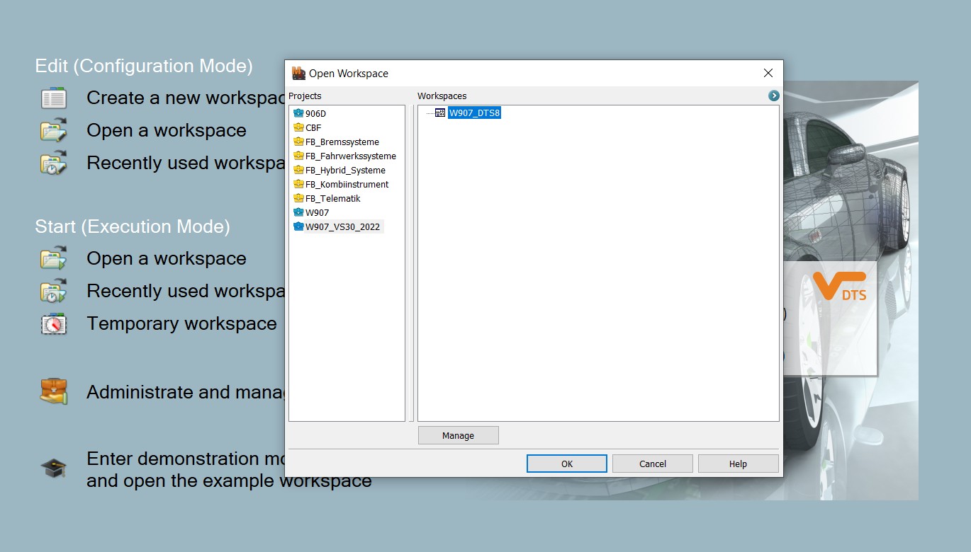
Begin by connecting DTS Monaco to the vehicle and performing a quick scan of all ECUs to identify any stored diagnostic trouble codes (DTCs). Note any communication-related DTCs, as these indicate potential CAN bus issues.
6.2 Step 2: CAN Bus Monitoring with a CAN Bus Analyzer
Connect a CAN bus analyzer to the vehicle and begin monitoring CAN bus traffic. Filter the data to focus on the ECUs or CAN IDs related to the DTCs identified in Step 1. Look for missing messages, corrupted data, or excessive error frames.
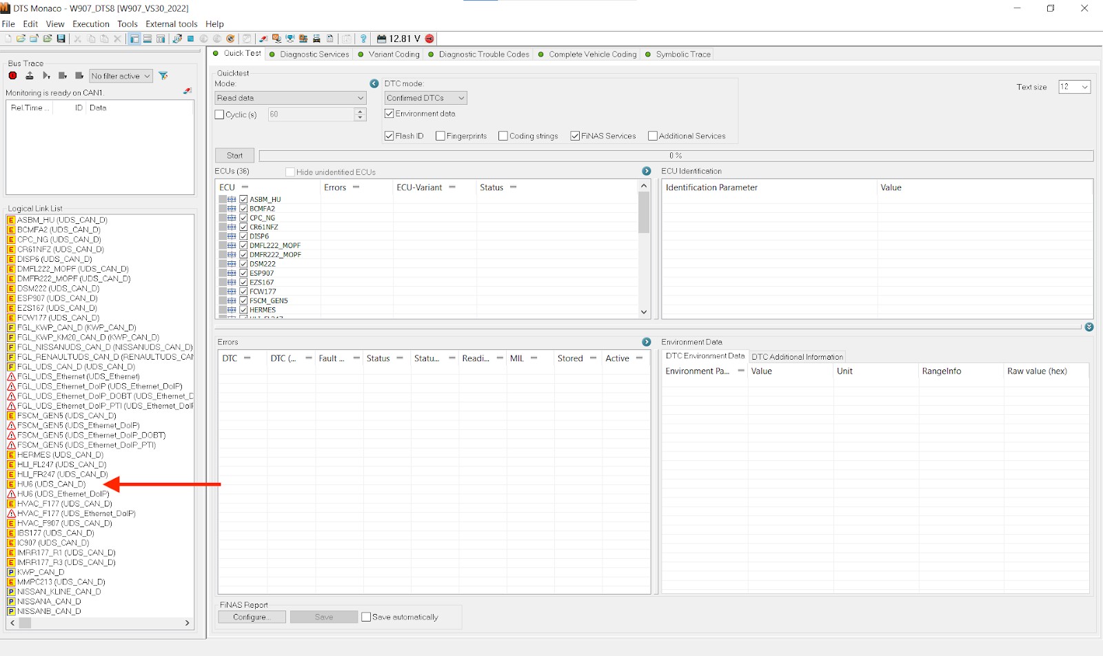 DTS Monaco Interface
6.3 Step 3: Signal Integrity Analysis with an Oscilloscope
Connect an oscilloscope to the CAN High and CAN Low wires of the affected CAN bus segment. Check the signal waveforms for proper voltage levels, timing, and signal integrity. Look for signs of noise, reflections, or voltage drops that could indicate wiring or termination issues.
6.4 Step 4: Correlation and Root Cause Identification
Correlate the data from DTS Monaco, the CAN bus analyzer, and the oscilloscope to identify the root cause of the communication issues. For example, if DTS Monaco reports a communication error with the ABS module, the CAN bus analyzer shows missing ABS messages, and the oscilloscope reveals voltage drops during ABS operation, the problem is likely a wiring or power supply issue affecting the ABS module.
6.5 Step 5: Verification and Repair
After identifying the root cause, perform the necessary repairs, such as replacing faulty wiring, repairing connectors, or replacing a malfunctioning ECU. After the repair, use DTS Monaco to clear the DTCs and verify that the communication issues have been resolved.
7. Advanced Diagnostic Techniques
Advanced diagnostic techniques can further enhance the effectiveness of CAN bus diagnostics with DTS Monaco and complementary tools.
7.1 Bus Load Analysis
Use a CAN bus analyzer to measure the bus load, which is the percentage of time the CAN bus is occupied with transmitting messages. High bus load (above 80%) can lead to communication delays and errors. Identify the ECUs or messages contributing to the high bus load and optimize their communication patterns.
7.2 Error Frame Analysis
Analyze the error frames captured by the CAN bus analyzer to identify the types and sources of errors on the CAN bus. Common error types include bit errors, CRC errors, and form errors. Identifying the source of these errors can help pinpoint faulty ECUs or wiring issues.
7.3 Jitter Analysis
Use an oscilloscope to measure the jitter, which is the variation in the timing of CAN bus signals. Excessive jitter can lead to communication errors and is often caused by clock synchronization issues or electromagnetic interference (EMI).
7.4 Simulation and Emulation
Use a CAN bus simulator to simulate the behavior of specific ECUs or CAN bus segments. This can help isolate and diagnose issues in a controlled environment without affecting the entire vehicle.
7.5 Data Logging and Analysis
Use a CAN bus data logger to record CAN bus traffic over an extended period. Analyze the logged data to identify intermittent issues or patterns that are difficult to detect in real-time.
8. Common CAN Bus Problems and Their Solutions
Understanding common CAN bus problems and their solutions can streamline the diagnostic process.
8.1 Wiring Issues
- Problem: Damaged or corroded wiring can cause signal degradation, intermittent communication errors, or complete loss of communication.
- Solution: Inspect the wiring for damage, corrosion, or loose connections. Repair or replace any faulty wiring segments.
8.2 Termination Resistor Problems
- Problem: Incorrect or missing termination resistors can cause signal reflections and communication errors.
- Solution: Verify that the CAN bus is properly terminated with 120-ohm resistors at each end of the bus. Replace any faulty termination resistors.
8.3 ECU Failures
- Problem: A malfunctioning ECU can cause communication errors, missing messages, or bus conflicts.
- Solution: Use DTS Monaco to diagnose the ECU and check for internal faults. Replace the ECU if necessary.
8.4 Grounding Issues
- Problem: Poor grounding can cause noise and voltage drops on the CAN bus, leading to communication errors.
- Solution: Verify that all ECUs and components are properly grounded. Clean or repair any corroded ground connections.
8.5 Software Bugs
- Problem: Software bugs in an ECU can cause communication errors or unexpected behavior on the CAN bus.
- Solution: Update the ECU software to the latest version using DTS Monaco or another compatible programming tool.
9. Best Practices for CAN Bus Diagnostics
Following best practices can improve the accuracy and efficiency of CAN bus diagnostics.
9.1 Use High-Quality Diagnostic Tools
Invest in high-quality oscilloscopes, CAN bus analyzers, and specialized adapters from reputable manufacturers. These tools provide accurate and reliable data, improving the accuracy of your diagnoses.
9.2 Follow Proper Connection Procedures
Always follow proper connection procedures when connecting diagnostic tools to the vehicle’s CAN bus. Use appropriate adapters and connectors, and ensure proper grounding and termination.
9.3 Document Your Work
Keep detailed records of your diagnostic procedures, measurements, and findings. This documentation can help you track down intermittent issues and identify patterns.
9.4 Stay Up-to-Date
Stay up-to-date with the latest CAN bus standards, diagnostic techniques, and troubleshooting tips. Attend training courses and workshops to improve your skills.
9.5 Seek Expert Advice
Don’t hesitate to seek expert advice when you encounter complex or difficult-to-diagnose CAN bus issues. Consult with experienced technicians or contact the tool manufacturers for support.
10. Why Choose MERCEDES-DIAGNOSTIC-TOOL.EDU.VN for Your Diagnostic Needs
At MERCEDES-DIAGNOSTIC-TOOL.EDU.VN, we understand the complexities of CAN bus diagnostics in Mercedes-Benz vehicles. We provide comprehensive resources, expert guidance, and a wide range of diagnostic tools to help you effectively troubleshoot and resolve communication issues.
10.1 Expert Guidance and Support
Our team of experienced technicians and engineers is available to provide expert guidance and support for all your diagnostic needs. Whether you need help selecting the right tools, interpreting diagnostic data, or troubleshooting complex issues, we are here to assist you.
10.2 Comprehensive Resources
We offer a comprehensive library of resources, including diagnostic guides, troubleshooting tips, and training materials. These resources are designed to help you improve your diagnostic skills and stay up-to-date with the latest technologies.
10.3 High-Quality Diagnostic Tools
We offer a wide range of high-quality diagnostic tools from reputable manufacturers. Our selection includes oscilloscopes, CAN bus analyzers, specialized adapters, and other essential tools for CAN bus diagnostics.
10.4 Customized Solutions
We understand that every diagnostic situation is unique. That’s why we offer customized solutions tailored to your specific needs and requirements. Whether you are a professional technician or a DIY enthusiast, we can help you find the right tools and resources to get the job done.
10.5 Contact Us Today
Don’t let CAN bus issues slow you down. Contact us today at 789 Oak Avenue, Miami, FL 33101, United States or via Whatsapp at +1 (641) 206-8880. Visit our website at MERCEDES-DIAGNOSTIC-TOOL.EDU.VN for more information and to explore our range of diagnostic tools and resources. Let MERCEDES-DIAGNOSTIC-TOOL.EDU.VN be your trusted partner in CAN bus diagnostics.
FAQ: CAN Bus Diagnostics with DTS Monaco
What is the best diagnostic tool for Mercedes-Benz CAN bus systems?
DTS Monaco, when paired with tools like oscilloscopes and CAN bus analyzers, provides comprehensive diagnostic capabilities for Mercedes-Benz CAN bus systems.
How do I unlock hidden features on my Mercedes using DTS Monaco?
Unlocking hidden features involves accessing specific ECUs via DTS Monaco, disabling firewalls, and modifying variant coding parameters; however, this should be done with caution and proper knowledge.
How often should I perform maintenance on my Mercedes-Benz?
Regular maintenance, typically every 10,000 miles or once a year, is crucial for optimal performance and longevity of your Mercedes-Benz vehicle.
What are the common issues with Mercedes-Benz CAN bus systems?
Common issues include wiring problems, termination resistor faults, ECU failures, grounding issues, and software bugs, all affecting communication between vehicle modules.
Can I use DTS Monaco to reprogram ECUs?
Yes, DTS Monaco can be used to reprogram ECUs, update software, and flash new firmware, allowing for advanced customization and repair.
Is it safe to modify ECU parameters using DTS Monaco?
Modifying ECU parameters should be done with caution, as incorrect settings can lead to vehicle malfunction. Proper documentation and backups are essential.
What is a CAN bus analyzer, and why is it useful?
A CAN bus analyzer captures and interprets CAN bus traffic, helping identify communication errors, bus overloads, and missing messages for accurate diagnostics.
How does an oscilloscope aid in CAN bus diagnostics?
An oscilloscope visualizes electrical signals, helping identify signal integrity issues like noise, signal reflections, and voltage drops affecting CAN bus communication.
What are the key features to look for in a CAN bus adapter?
Key features include CAN bus speed support, galvanic isolation, ruggedness, and compliance with automotive standards to ensure reliable and safe diagnostics.
Where can I find reliable resources for learning CAN bus diagnostics?
Reliable resources include automotive engineering handbooks, diagnostic guides from tool manufacturers, and expert advice from professionals at MERCEDES-DIAGNOSTIC-TOOL.EDU.VN.