The Controller Area Network (CAN) bus is a critical communication system in modern vehicles, enabling Electronic Control Units (ECUs) to communicate efficiently. At MERCEDES-DIAGNOSTIC-TOOL.EDU.VN, we want to show you how understanding the CAN bus can improve your ability to interpret Mercedes live data, optimize performance, and troubleshoot issues effectively. Explore how to unlock hidden features and ensure your Mercedes runs at its best with our expert guidance on automotive diagnostics, ECU programming, and vehicle customization.
Contents
- 1. Understanding the CAN Bus System
- 1.1. The Body’s Nervous System Analogy
- 1.2. Physical Composition of the CAN Bus
- 1.3. Defining Electronic Control Units (ECUs)
- 1.4. ECU’s Primary Elements
- 1.5. Connecting to the CAN Bus with DB9 Connector
- 2. Different Variants of the CAN Bus
- 2.1. Other Automotive Networks
- 3. Key Benefits of Using the CAN Bus
- 3.1. Simplicity and Low Cost
- 3.2. Centralized Access and Diagnostics
- 3.3. Robustness and Reliability
- 3.4. Efficiency and Prioritization
- 4. The CAN Bus History in Short
- 5. The Future of the CAN Bus
- 6. The CAN Bus Physical and Data Link Layer
- 6.1. Physical Layer (ISO 11898-2)
- 6.2. Data Link Layer (ISO 11898-1)
- 7. What is a CAN Frame?
- 7.1. CAN Frame Variants
- 8. Higher-Layer CAN Protocols
- 8.1. Common Automotive/Industrial CAN Protocols
- 8.2. Analogy of Communication
- 8.3. Other Higher-Layer CAN Protocols
- 9. How to Log CAN Bus Data
- 9.1. Select the Right Hardware
- 9.2. Identify the Adapter Cable
- 9.3. Adapter Selection Tips
- 9.4. Multiple CAN Buses
- 9.5. Configure and Connect Your Device
- 9.6. Review Your Raw CAN Data
- 10. How to Decode Raw CAN Data to ‘Physical Values’
- 10.1. Understand CAN Signal Extraction
- 10.2. Get the Relevant DBC File
- 10.3. DBC File Access
- 10.4. Use a Software/API Tool
- 10.5. Logging CAN Data – Example Use Cases
- FAQ: Unlocking the Secrets of CAN Bus for Mercedes Diagnostics
- 1. What is the CAN bus and why is it important for Mercedes vehicles?
- 2. How does the CAN bus transmit live data in a Mercedes?
- 3. What types of data can be accessed via the CAN bus in a Mercedes?
- 4. What tools are needed to read CAN bus data from a Mercedes?
- 5. Can I use any OBD2 scanner to read CAN bus data from my Mercedes?
- 6. How can I use CAN bus data to diagnose issues in my Mercedes?
- 7. Is it possible to modify vehicle settings or parameters via the CAN bus in a Mercedes?
- 8. Are there any risks involved in accessing or modifying CAN bus data in a Mercedes?
- 9. How can I ensure the security of my Mercedes’ CAN bus system?
- 10. Where can I learn more about CAN bus diagnostics and Mercedes-specific applications?
- Take Action Today
1. Understanding the CAN Bus System
The CAN bus (Controller Area Network) is a specialized communication network that allows various components inside a vehicle to communicate with each other without needing a central host computer. This robust system allows microcontrollers and devices to communicate within a vehicle without a host computer. This means components like the engine control unit, transmission, anti-lock braking system, and other electronic control units can share data and coordinate actions in real time.
1.1. The Body’s Nervous System Analogy
Think of the CAN bus as a car’s nervous system: it transmits information rapidly and reliably between different parts. ECUs (Electronic Control Units) are like parts of the body, interconnected via the CAN bus, sharing information sensed by one part with others.
1.2. Physical Composition of the CAN Bus
Physically, all ECUs are connected through a two-wire bus system that includes a twisted pair: CAN high and CAN low. These wires are often color-coded, with CAN high typically being yellow and CAN low being green.
1.3. Defining Electronic Control Units (ECUs)
Electronic Control Units (ECUs) control specific functions in a vehicle, such as engine management, transmission, braking, and steering. Modern cars may have over 70 ECUs, each sharing data on the CAN bus. Any ECU can broadcast information, and other ECUs decide whether to accept or ignore it.
1.4. ECU’s Primary Elements
An ECU comprises three primary elements:
- Microcontroller: Interprets incoming CAN messages and decides what messages to transmit.
- CAN Controller: Manages communication according to the CAN protocol, including message encoding, error detection, and arbitration.
- CAN Transceiver: Connects the CAN controller to the physical CAN wires, converting data into signals for the CAN bus and providing electrical protection.
1.5. Connecting to the CAN Bus with DB9 Connector
While there is no universal connector for CAN bus applications, the CAN DB9 (D-sub9) connector (CANopen CiA 303-1) is a common choice for CAN bus data loggers and interfaces.
2. Different Variants of the CAN Bus
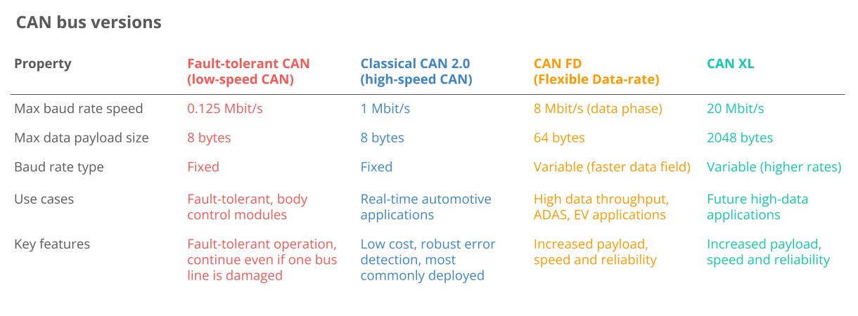
Multiple CAN variants exist, each designed for specific applications and performance requirements:
- Low-Speed CAN: A fault-tolerant option ideal for critical applications, though it’s increasingly replaced by LIN bus.
- High-Speed CAN: The most common variant used in automotive and machinery applications.
- CAN FD: Offers longer payloads and faster speeds, providing enhanced performance. For more information, refer to our CAN FD introduction at MERCEDES-DIAGNOSTIC-TOOL.EDU.VN.
- CAN XL: Provides even longer payloads and faster speeds, bridging the gap between CAN and Automotive Ethernet.
 Classical CAN FD XL Variants canbus
2.1. Other Automotive Networks
In addition to CAN, other networks are used in vehicles:
- LIN Bus: A lower-cost supplement to CAN bus, suitable for less critical functions like air conditioning and door controls. Check our LIN bus introduction or LIN bus data logger article at MERCEDES-DIAGNOSTIC-TOOL.EDU.VN.
- FlexRay: Offers higher speeds (up to 10 Mbit/s) and fault tolerance but is more expensive.
- Automotive Ethernet: Increasingly used for high-bandwidth applications like ADAS (Advanced Driver Assistance Systems) and infotainment, providing high data transfer rates.
3. Key Benefits of Using the CAN Bus
The CAN bus standard is used in virtually all vehicles and many machines due to its benefits.
3.1. Simplicity and Low Cost
ECUs communicate through a single CAN system instead of complex direct analog signal lines, reducing errors, weight, wiring, and costs. Traditional point-to-point wiring systems require dedicated wires between nodes, making the system costly and inflexible. Switching to CAN bus can reduce a vehicle’s wiring harness weight by up to 20 kg, lowering fuel costs.
3.2. Centralized Access and Diagnostics
The CAN bus offers a single point of entry for communicating with all network ECUs, allowing central diagnostics, data logging, and configuration. Centralized diagnostics enable direct access to all CAN bus traffic from any point on the network, simplifying diagnostics. Silent CAN logging ensures the device does not affect the CAN bus, which is critical for diagnostics.
3.3. Robustness and Reliability
The CAN bus system is robust to electrical disturbances and electromagnetic interference, making it ideal for safety-critical applications. Differential signaling ensures that electromagnetic interference affects both lines equally, making the signal robust against environmental noise. CAN ensures data integrity through extensive error detection, including bit errors, stuff errors, CRC errors, form errors, and ACK errors. Nodes can automatically retransmit faulty messages.
3.4. Efficiency and Prioritization
CAN frames are prioritized by ID, so high-priority data gets immediate bus access without interrupting other frames. Arbitration ensures that the frame with the lowest CAN ID (highest priority) wins when multiple nodes attempt to transmit data. This avoids collisions and prioritizes safety-critical messages.
4. The CAN Bus History in Short
- Pre-CAN: Car ECUs relied on complex point-to-point wiring.
- 1986: Bosch developed the CAN protocol.
- 1991: Bosch published CAN 2.0 (CAN 2.0A: 11 bit, 2.0B: 29 bit).
- 1993: CAN is adopted as an international standard (ISO 11898).
- 2003: ISO 11898 becomes a standard series.
- 2012: Bosch released CAN FD 1.0 (flexible data rate).
- 2015: The CAN FD protocol is standardized (ISO 11898-1).
- 2016: The physical CAN layer for data rates up to 5 Mbit/s is standardized in ISO 11898-2.
- 2018: CiA starts development of CAN XL.
- 2024: CAN XL standardized (ISO 11898-1:2024, 11898-2:2024)
Today, CAN is standard in automotives (cars, trucks, buses, tractors), ships, planes, EV batteries, and machinery.
5. The Future of the CAN Bus
Looking ahead, the CAN bus protocol will remain relevant, impacted by these major trends:
- Need for Speed: Demand for higher data rates may drive transition towards CAN FD, CAN XL, or Automotive Ethernet.
- Connected Vehicles: Rise of cloud computing and vehicle telematics may enable predictive maintenance and remote troubleshooting but also cybersecurity risks.
- Open vs. Closed: A push towards ‘Open Source’ and ‘Right to Repair’ may conflict with OEM demands for proprietary data to offer subscription-based microservices.
The transition from Classical CAN to CAN FD, CAN XL, or Automotive Ethernet will likely be slow. Despite CAN FD’s promise, Classical CAN remains dominant. Automotive Ethernet is increasingly important, especially in OEM R&D, but Classical CAN continues to be widely used in vehicles on the road.
6. The CAN Bus Physical and Data Link Layer
The controller area network is described by a data link layer and physical layer. For high-speed CAN, ISO 11898-1 describes the data link layer, while ISO 11898-2 describes the physical layer. In the context of a 7 layer OSI model, CAN thus represents the two lowest layers as illustrated.
6.1. Physical Layer (ISO 11898-2)
The CAN bus physical layer defines cable types, electrical signal levels, node requirements, and cable impedance. For example, the physical layer specifies the following:
- Baud Rate: Nodes must connect via a two-wire bus with baud rates up to 1 Mbit/s (Classical CAN) or 8 Mbit/s (CAN FD).
- Cable Length: Maximal CAN cable lengths should be between 500 meters (125 kbit/s) and 40 meters (1 Mbit/s).
- Termination: The CAN bus must be terminated using a 120 Ohm termination resistor at each end of the bus.
6.2. Data Link Layer (ISO 11898-1)
The CAN bus data link layer defines CAN frame formats, error handling, and data transmission to ensure data integrity. For example, the data link layer specifies:
- Frame Formats: Four types (data frames, remote frames, error frames, overload frames) and 11-bit/29-bit identifiers.
- Error Handling: Methods for detecting/handling CAN errors, including CRC, acknowledgement slots, and error counters.
- Arbitration: Non-destructive bitwise arbitration helps manage CAN bus access and avoid collisions via ID-based priority.
7. What is a CAN Frame?
Communication over the CAN bus occurs via CAN frames, as per the data link layer. Below is a standard CAN data frame with an 11-bit identifier (CAN 2.0A), commonly used in most cars. The extended 29-bit identifier frame (CAN 2.0B) is identical, except for the longer ID, and is used in protocols like J1939 for heavy-duty vehicles.
- SOF: Start of Frame indicates a CAN node intends to communicate.
- ID: The frame identifier, with lower values having higher priority.
- RTR: Remote Transmission Request indicates if a node sends data or requests data from another node.
- Control: Contains the Identifier Extension Bit (IDE) and the Data Length Code (DLC), which specifies the length of the data to be transmitted.
- Data: Contains the data bytes, including CAN signals that can be decoded for information.
- CRC: Cyclic Redundancy Check is used to ensure data integrity.
- ACK: Acknowledgment slot indicates if the node has received the data correctly.
- EOF: Marks the end of the CAN frame.
7.1. CAN Frame Variants
Four CAN frame variants exist:
- Data Frame: Carries data from a sender node to one or more receiver nodes.
- Error Frame: Indicates the detection of a communication error.
- Remote Frame: Requests data from a CAN node.
- Overload Frame: Provides additional delay between CAN frames if nodes require more processing time.
The CAN frame must meet specific properties to be valid. Erroneous frames are automatically detected, triggering CAN bus error handling, where nodes track their error counters and change state to avoid further errors.
8. Higher-Layer CAN Protocols
As a lower-layer protocol, CAN provides a basis for communication. Higher-layer protocols detail how data is communicated between CAN nodes.
8.1. Common Automotive/Industrial CAN Protocols
-
OBD2 (On-Board Diagnostics): Used in cars and trucks for diagnostics and maintenance, specifying diagnostic trouble codes (DTCs) and real-time data like speed and RPM. At MERCEDES-DIAGNOSTIC-TOOL.EDU.VN, we help you leverage OBD2 for optimal vehicle maintenance.
-
UDS (Unified Diagnostic Services): A communication protocol for automotive ECUs, enabling diagnostics, firmware updates, and routine testing. Learn more about UDS protocols via our resources.
-
CCP/XCP (CAN Calibration Protocol/Universal Measurement and Calibration Protocol): Enables ECU read/write access for calibration, measurement, and flashing.
-
CANopen: Widely used in embedded control applications, including industrial automation, to enable interoperability between CAN nodes.
-
SAE J1939: Used in heavy-duty vehicles, where parameters like speed are identified by a suspect parameter number (SPN) and grouped by parameter group numbers (PGN).
-
NMEA 2000: Used in the maritime industry for connecting engines, instruments, and sensors on boats, based on CAN and closely linked to J1939.
-
ISOBUS (ISO 11783): Used in agriculture and forestry machinery, enabling plug-and-play integration between vehicles and implements across brands, closely linked to J1939.
8.2. Analogy of Communication
Think of people communicating: CAN bus defines the physical requirements and basic building blocks, while higher-layer protocols reflect different languages. Here are some observations:
- Always a Higher-Layer Protocol: Practical applications always use a higher-layer protocol.
- Thousands of Protocols Exist: Like languages, many higher-layer protocols exist, including custom protocols.
- Recording vs. Understanding Data: A sound recorder can record any conversation, just like a CAN bus data logger can record any CAN communication. However, interpreting the information requires understanding the higher-layer protocol.
- Multiple Protocols: Your car uses a CAN-based higher-layer protocol for most data communication, but it can also communicate via OBD2 or UDS for diagnostics.
- Interoperability: Standardized higher-layer protocols provide fundamental interoperability, leveraging the language (e.g., J1939) across many use cases.
8.3. Other Higher-Layer CAN Protocols
- ARINC: Used in the aerospace industry.
- UAVCAN: Used in drones, aerospace, and robotics.
- DeviceNet: Used in industrial automation.
- SafetyBUS p: Used in safety-critical industrial automation.
- MilCAN: Designed for military vehicles.
- HVAC CAN: Designed for HVAC systems in buildings and vehicles.
9. How to Log CAN Bus Data
Follow these steps to log raw CAN bus data effectively.
9.1. Select the Right Hardware
Decide how you wish to collect the CAN data.
9.2. Identify the Adapter Cable
Determine the appropriate adapter for your application. Here are four common options:
- OBD2 Adapter: For cars and some vans/trucks, allowing you to request OBD2/UDS data and access proprietary CAN data.
- J1939 Adapter: For heavy-duty vehicles, providing access to raw CAN data (J1939 protocol).
- M12 Adapter: For maritime vessels and some industrial machinery, allowing you to record raw CAN data (NMEA 2000 or CANopen).
- Contactless CAN Reader: A universal option using induction to read data from the CAN high/low wiring harness directly.
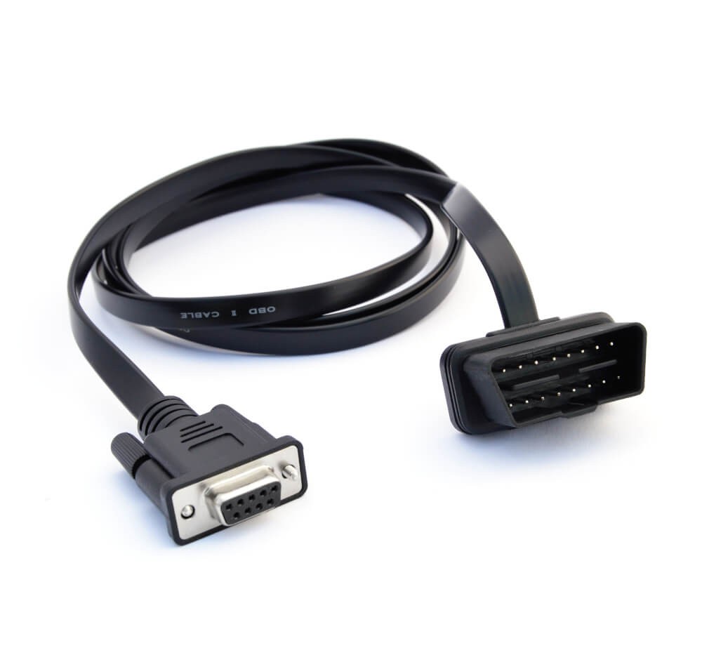 On Board Diagnostic OBD2 Connector Adapter
9.3. Adapter Selection Tips
Here are additional tips based on the type of use case:
- Cars: Use the OBD2 adapter to request OBD2 data. For EVs, you may perform UDS requests.
- Heavy-Duty: The J1939 adapter is most common, but other connectors may be used.
- Maritime: Use the M12 connector for NMEA 2000 data.
- Industrial Machinery: The M12 adapter is often used.
- Agriculture: Use the J1939 adapter for J1939 data or the in-cab adapter to access the ISOBUS network.
- Labs & Test Benches: Use a generic adapter that provides open-wire connections.
- Universal: Contactless CAN readers can always be used as long as you can access the physical CAN bus wiring.
9.4. Multiple CAN Buses
Many modern vehicles have multiple CAN buses and other automotive protocols like LIN bus, FlexRay, and Automotive Ethernet. You may need to connect to multiple buses in parallel to collect all necessary data, using CAN loggers that allow logging of multiple CAN networks in time synchronization.
9.5. Configure and Connect Your Device
Before connecting your device, consider these:
- Baud Rate: Must match the CAN bus. Some devices auto-detect the baud rate.
- Requests: Configure your device to transmit relevant request messages if you aim to record on-request data like OBD2/UDS.
Connect your device and verify it logs data. If not, troubleshoot using our tips at MERCEDES-DIAGNOSTIC-TOOL.EDU.VN.
9.6. Review Your Raw CAN Data
After recording, review the resulting log file. Raw CAN bus data is not human-readable, requiring decoding to interpret.
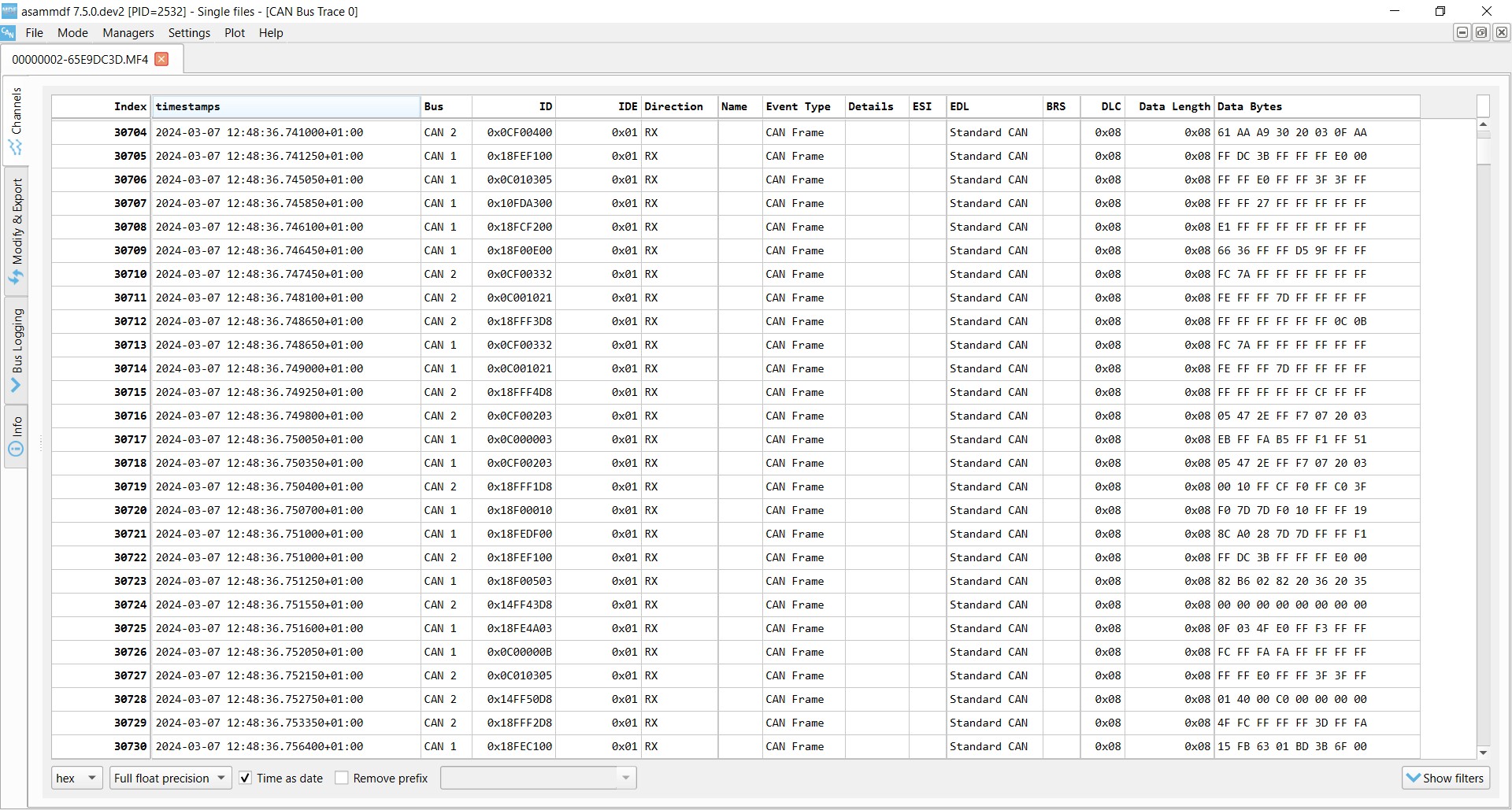 Raw CAN bus data example asammdf J1939
10. How to Decode Raw CAN Data to ‘Physical Values’
To interpret raw CAN data, you need to decode the CAN frames into scaled engineering values (km/h, degrees). This requires a DBC file and software tool.
10.1. Understand CAN Signal Extraction
Each CAN frame contains CAN signals in the data payload. Extracting the physical value of a CAN signal requires:
- Byte Order: Whether data is encoded Intel or Motorola.
- Bit Start: The bit at which the signal starts.
- Bit Length: The length of the signal in bits.
- Offset: Value to offset the signal value by.
- Scale: Value to multiply the signal value by.
10.2. Get the Relevant DBC File
A CAN DBC file contains information for decoding raw CAN data. DBC files are typically application-specific and proprietary, available from the OEM.
10.3. DBC File Access
If you are an OEM engineer, you typically have the DBC or the information to create one. If not, consider these routes:
- Standardized DBC Files: Use standardized DBC files like J1939, NMEA 2000, ISOBUS, or OBD2 if applicable.
- Reverse Engineering: Reverse engineer the CAN bus to create a DBC file.
- DBC Creator: Use a CAN DBC creator that enables CAN bus reverse engineering.
- OEM: Obtain the DBC through official channels.
10.4. Use a Software/API Tool
You need a software/API tool that supports your log file format and DBC files.
- asammdf GUI: Useful for ad hoc analysis, diagnostics, and export.
- Grafana Dashboards: Customized dashboards enable data visualization and reporting.
- MATLAB/Python: Script tools enable statistical analysis and big data processing.
10.5. Logging CAN Data – Example Use Cases
Common use cases for recording CAN bus data include:
- Logging/Streaming Data from Cars: OBD2 data can be used to reduce fuel costs and improve driving.
- Heavy-Duty Fleet Telematics: J1939 data can be used in fleet management to reduce costs.
- Predictive Maintenance: IoT CAN loggers in the cloud can monitor vehicles and machinery to predict breakdowns.
- Vehicle/Machine Blackbox: CAN loggers can serve as ‘black boxes’ for vehicles or equipment, providing data for disputes or diagnostics.
FAQ: Unlocking the Secrets of CAN Bus for Mercedes Diagnostics
1. What is the CAN bus and why is it important for Mercedes vehicles?
The CAN bus (Controller Area Network) is a critical communication system in Mercedes vehicles, enabling various electronic components to communicate without a central computer. It enhances diagnostics, performance tuning, and overall vehicle management.
2. How does the CAN bus transmit live data in a Mercedes?
The CAN bus transmits live data by allowing ECUs to broadcast information across the network, where other ECUs can choose to receive or ignore the data. This facilitates real-time monitoring and control of various vehicle parameters.
3. What types of data can be accessed via the CAN bus in a Mercedes?
You can access a wide array of data, including engine RPM, vehicle speed, sensor readings (temperature, pressure), diagnostic trouble codes (DTCs), and the status of various systems (ABS, SRS) within the Mercedes.
4. What tools are needed to read CAN bus data from a Mercedes?
To read CAN bus data, you will need a diagnostic tool that supports CAN bus communication, such as an OBD2 scanner, a CAN bus data logger, and appropriate software for data interpretation.
5. Can I use any OBD2 scanner to read CAN bus data from my Mercedes?
While most OBD2 scanners can read basic CAN bus data, advanced diagnostics and accessing Mercedes-specific parameters may require a professional-grade scanner or software designed for Mercedes vehicles.
6. How can I use CAN bus data to diagnose issues in my Mercedes?
By reading and interpreting CAN bus data, you can identify abnormal sensor readings, communication errors, and fault codes, which helps pinpoint the root cause of issues and guide effective repairs.
7. Is it possible to modify vehicle settings or parameters via the CAN bus in a Mercedes?
Yes, with the right tools and expertise, you can modify certain vehicle settings, such as enabling/disabling features, adjusting performance parameters, or performing ECU programming, through the CAN bus.
8. Are there any risks involved in accessing or modifying CAN bus data in a Mercedes?
Yes, improper access or modification can lead to system malfunctions, data corruption, or even damage to the vehicle’s electronic components. It’s crucial to have a thorough understanding and use reliable tools.
9. How can I ensure the security of my Mercedes’ CAN bus system?
To ensure security, use trusted diagnostic tools, keep your vehicle’s software updated, and be cautious about connecting unauthorized devices to the OBD2 port. Implementing security protocols can further protect your CAN bus system.
10. Where can I learn more about CAN bus diagnostics and Mercedes-specific applications?
You can learn more through professional training courses, online forums, and resources provided by MERCEDES-DIAGNOSTIC-TOOL.EDU.VN, which offer detailed guides and support for Mercedes diagnostics and CAN bus applications.
Do you have a CAN logging use case? Contact us for free sparring at MERCEDES-DIAGNOSTIC-TOOL.EDU.VN.
Take Action Today
Ready to unlock the full potential of your Mercedes? Understanding the CAN bus system is the first step. At MERCEDES-DIAGNOSTIC-TOOL.EDU.VN, we provide the tools, knowledge, and support you need.
Contact us today for personalized assistance:
- Address: 789 Oak Avenue, Miami, FL 33101, United States
- WhatsApp: +1 (641) 206-8880
- Website: MERCEDES-DIAGNOSTIC-TOOL.EDU.VN
Whether you’re looking for the right diagnostic tools, guidance on unlocking hidden features, or expert advice on repairs and maintenance, we’re here to help. Let us help you elevate your Mercedes ownership experience.