Are you curious about connecting your Arduino to your car’s OBD2 port via WiFi for DIY diagnostics and data logging? Yes, it is indeed possible to connect an Arduino to an OBD2 WiFi interface, allowing you to retrieve valuable data from your vehicle and customize your driving experience, which MERCEDES-DIAGNOSTIC-TOOL.EDU.VN can help you achieve. By understanding the ELM327 command set and OBD PIDs, you can unlock a world of possibilities for vehicle monitoring and customization, enhancing car performance, real-time data and DIY car diagnostics.
Contents
- 1. Understanding the Basics of OBD2 and ELM327
- 1.1. What is OBD2?
- 1.2. The Role of ELM327
- 1.3. Why Use Arduino with OBD2?
- 1.4. Key Protocols Used in OBD2
- 2. Essential Components for Your DIY Project
- 2.1. Arduino Board
- 2.2. ELM327 OBD2 WiFi Adapter
- 2.3. OBD2 Extension Cable (Optional)
- 2.4. Logic Level Converter (If Needed)
- 2.5. Power Supply
- 2.6. WiFi Module
- 2.7. Jumper Wires and Breadboard
- 3. Setting Up Your Arduino and WiFi Module
- 3.1. Installing the Arduino IDE
- 3.2. Connecting the WiFi Module to Arduino
- 3.3. Configuring the WiFi Module
- 3.4. Testing the WiFi Connection
- 4. Connecting the ELM327 to Your Arduino
- 4.1. Physical Connections
- 4.2. Using a Logic Level Converter
- 4.3. Powering the ELM327 Adapter
- 5. Arduino Code for OBD2 Communication
- 5.1. Initializing the Serial Connection
- 5.2. Sending AT Commands to the ELM327
- 5.3. Requesting Data Using OBD PIDs
- 5.4. Parsing the Response
- 5.5. Example Code Snippet
- 6. Sending Data Over WiFi
- 6.1. Connecting to WiFi
- 6.2. Sending Data to a Server
- 6.3. Using MQTT
- 7. Potential Challenges and Solutions
- 7.1. Compatibility Issues
- 7.2. Data Overload
- 7.3. Security Concerns
- 7.4. Power Management
- 8. Advanced Applications and Customization
- 8.1. Creating a Custom Dashboard
- 8.2. Data Logging and Analysis
- 8.3. Remote Monitoring
- 8.4. Integration with Home Automation Systems
- 9. Safety Precautions and Legal Considerations
- 9.1. Do Not Distract Yourself While Driving
- 9.2. Be Aware of Local Laws
- 9.3. Protect Your Vehicle’s Security
- 10. The Future of DIY Car Diagnostics
- 10.1. Advancements in OBD2 Technology
- 10.2. The Rise of Connected Cars
- 10.3. The Role of DIY Enthusiasts
- 11. Step-by-Step Guide: DIY Connect Arduino to OBD2 WiFi
- 11.1. Gather Your Components
- 11.2. Connect the Hardware
- 11.3. Install the Arduino IDE and Libraries
- 11.4. Write the Arduino Code
- 11.5. Upload the Code to Arduino
- 11.6. Test the Connection
- 12. Understanding Search Intent
- 13. Common AT Commands for ELM327
- 14. OBD2 PIDs for Data Retrieval
- 15. FAQ: Connecting Arduino to OBD2 WiFi
- 16. Conclusion: Unleash Your Car’s Potential with DIY Diagnostics
1. Understanding the Basics of OBD2 and ELM327
1.1. What is OBD2?
OBD2, or On-Board Diagnostics II, is a standardized system used in most vehicles since 1996 to monitor and control various engine and emissions-related parameters. This system allows you or a technician to access valuable information about your vehicle’s performance and identify potential issues. According to the EPA, OBD2 was mandated to ensure vehicles meet emissions standards.
1.2. The Role of ELM327
The ELM327 is a microcontroller chip that acts as a translator between your car’s OBD2 protocol and a more user-friendly interface, such as a serial connection or WiFi. It essentially converts the complex signals from your car’s ECU (Engine Control Unit) into readable data that can be interpreted by devices like an Arduino. Elm Electronics originally created the ELM327, establishing it as the industry standard.
1.3. Why Use Arduino with OBD2?
Combining an Arduino with an OBD2 interface opens up a world of possibilities for DIY car diagnostics and customization. You can:
- Monitor real-time data: Track parameters like engine speed, coolant temperature, and fuel consumption.
- Read and clear diagnostic trouble codes (DTCs): Identify and resolve issues with your vehicle.
- Create custom dashboards: Display the data you want to see in a way that’s meaningful to you.
- Log data for analysis: Record vehicle data over time to identify trends and optimize performance.
1.4. Key Protocols Used in OBD2
OBD2 utilizes several communication protocols, with the most common including:
- SAE J1850 PWM and VPW: Used primarily by Ford and General Motors vehicles.
- ISO 9141-2: Commonly found in European and Asian vehicles.
- ISO 14230-4 (KWP2000): A more modern protocol used in a variety of vehicles.
- ISO 15765-4 (CAN): The current standard, used in most modern vehicles.
Understanding these protocols is crucial for ensuring compatibility between your OBD2 interface and your vehicle.
2. Essential Components for Your DIY Project
2.1. Arduino Board
The Arduino is the brains of your project, responsible for processing data from the OBD2 interface and displaying it or sending it over WiFi. Popular choices include the Arduino Uno, Nano, and Mega, depending on your project’s complexity and I/O requirements.
2.2. ELM327 OBD2 WiFi Adapter
This adapter plugs into your car’s OBD2 port and communicates wirelessly with your Arduino via WiFi. Ensure that the adapter supports the OBD2 protocols used by your vehicle. These adapters are widely available online, with prices varying based on quality and features.
2.3. OBD2 Extension Cable (Optional)
An extension cable can be useful for easier access to the OBD2 port, especially if it’s in an awkward location. It can also help prevent damage to the adapter or the OBD2 port itself.
2.4. Logic Level Converter (If Needed)
Some ELM327 adapters operate at 3.3V, while the Arduino typically operates at 5V. A logic level converter ensures safe communication between the two devices by converting the voltage levels.
2.5. Power Supply
The Arduino can be powered via USB or an external power supply. For in-car use, consider using a 12V to 5V DC-DC converter to power the Arduino from the vehicle’s power system.
2.6. WiFi Module
Since your goal is to connect via WiFi, you’ll need a WiFi module compatible with your Arduino. Popular options include the ESP8266 and ESP32, which offer both WiFi and Bluetooth connectivity.
2.7. Jumper Wires and Breadboard
These are essential for connecting the various components of your project. A breadboard provides a convenient way to prototype your circuit before soldering.
3. Setting Up Your Arduino and WiFi Module
3.1. Installing the Arduino IDE
The Arduino IDE (Integrated Development Environment) is the software used to write and upload code to your Arduino board. Download the latest version from the official Arduino website and install it on your computer.
3.2. Connecting the WiFi Module to Arduino
Connect the WiFi module to your Arduino according to the manufacturer’s instructions. Typically, this involves connecting the module’s VCC, GND, TX, and RX pins to the corresponding pins on the Arduino.
3.3. Configuring the WiFi Module
Use the Arduino IDE to upload a sketch that configures the WiFi module to connect to your home or car’s WiFi network. This involves setting the SSID (network name) and password.
3.4. Testing the WiFi Connection
Once the WiFi module is configured, test the connection by sending data to a server or service on the internet. This ensures that the module is working correctly and that the Arduino can communicate over WiFi.
4. Connecting the ELM327 to Your Arduino
4.1. Physical Connections
Connect the ELM327 adapter to your Arduino using jumper wires. Typically, you’ll need to connect the adapter’s TX (transmit) pin to the Arduino’s RX (receive) pin, and the adapter’s RX pin to the Arduino’s TX pin. Also, connect the adapter’s power and ground pins to the Arduino’s 5V and GND pins, respectively.
4.2. Using a Logic Level Converter
If your ELM327 adapter operates at 3.3V, use a logic level converter to step down the Arduino’s 5V output to 3.3V for the adapter’s input, and step up the adapter’s 3.3V output to 5V for the Arduino’s input. This protects the adapter from damage.
4.3. Powering the ELM327 Adapter
The ELM327 adapter typically draws power from the OBD2 port. However, some adapters may require an external power supply. Ensure that the adapter is receiving the correct voltage and current.
5. Arduino Code for OBD2 Communication
5.1. Initializing the Serial Connection
In your Arduino code, initialize the serial connection between the Arduino and the ELM327 adapter. This involves setting the baud rate, which is the rate at which data is transmitted. Common baud rates for ELM327 adapters are 9600 and 38400.
void setup() {
  Serial.begin(38400); // Start serial communication
  delay(1000);
  Serial.println("Starting OBD2 Communication");
}
5.2. Sending AT Commands to the ELM327
The ELM327 adapter is controlled by a set of AT commands. These commands are used to configure the adapter, set the OBD2 protocol, and request data from the vehicle’s ECU.
void sendATCommand(String command) {
  Serial.println(command); // Send the command to the ELM327
  delay(500); // Wait for a response
  while (Serial.available() > 0) {
    String response = Serial.readStringUntil('r'); // Read the response
    Serial.println(response); // Print the response to the serial monitor
  }
}
5.3. Requesting Data Using OBD PIDs
OBD PIDs (Parameter IDs) are codes used to request specific data from the vehicle’s ECU. For example, PID 010C is used to request engine speed (RPM).
String getPIDValue(String pid) {
  Serial.print(pid); // Send the PID to the ELM327
  delay(500); // Wait for a response
  String response = Serial.readStringUntil('r'); // Read the response
  return response; // Return the response
}
5.4. Parsing the Response
The ELM327 adapter returns data in a specific format. You’ll need to parse the response to extract the desired value.
int parseRPM(String response) {
  // Remove unnecessary characters from the response
  response.replace("41 0C ", ""); // Remove header
  response.replace(" ", ""); // Remove spaces

  // Convert the hexadecimal value to an integer
  long rpmHex = strtol(response.c_str(), NULL, 16);

  // Calculate the RPM value
  int rpm = rpmHex / 4;

  return rpm;
}
5.5. Example Code Snippet
Here’s a simple example of Arduino code that requests engine RPM and prints it to the serial monitor:
void loop() {
  sendATCommand("ATZ"); // Reset ELM327
  sendATCommand("ATE0"); // Turn off echo
  sendATCommand("ATL0"); // Turn off linefeeds
  sendATCommand("ATS0"); // Turn off spaces
  sendATCommand("ATSP0"); // Set protocol to automatic

  String rpmResponse = getPIDValue("010C"); // Request engine RPM
  int rpm = parseRPM(rpmResponse); // Parse the response

  Serial.print("Engine RPM: ");
  Serial.println(rpm);

  delay(1000);
}
6. Sending Data Over WiFi
6.1. Connecting to WiFi
Before sending data, ensure that your Arduino is connected to the WiFi network.
#include <WiFi.h>

const char* ssid = "your_SSID";
const char* password = "your_PASSWORD";

void setup() {
  Serial.begin(115200);
  WiFi.begin(ssid, password);

  while (WiFi.status() != WL_CONNECTED) {
    delay(500);
    Serial.print(".");
  }

  Serial.println("Connected to WiFi");
}
6.2. Sending Data to a Server
You can send the OBD2 data to a server using HTTP or other protocols. Here’s an example of sending data using HTTP:
#include <HTTPClient.h>

void sendData(int rpm) {
  HTTPClient http;
  http.begin("http://your_server.com/api/data");
  http.addHeader("Content-Type", "application/json");

  String jsonData = "{"rpm":" + String(rpm) + "}";
  int httpResponseCode = http.POST(jsonData);

  if (httpResponseCode > 0) {
    Serial.print("HTTP Response code: ");
    Serial.println(httpResponseCode);
  } else {
    Serial.print("Error code: ");
    Serial.println(httpResponseCode);
  }

  http.end();
}

void loop() {
  // ... (OBD2 data retrieval code) ...
  sendData(rpm);
  delay(5000);
}
6.3. Using MQTT
MQTT (Message Queuing Telemetry Transport) is a lightweight protocol for sending data between devices. You can use an MQTT client library for Arduino to send OBD2 data to an MQTT broker.
7. Potential Challenges and Solutions
7.1. Compatibility Issues
Not all ELM327 adapters are created equal. Some may not support all OBD2 protocols or may have compatibility issues with certain vehicles. Research and choose an adapter that is known to work with your vehicle.
7.2. Data Overload
The OBD2 system can provide a lot of data. Processing and transmitting all of this data can be overwhelming for the Arduino and the WiFi connection. Prioritize the data you need and filter out the rest.
7.3. Security Concerns
Connecting your car to the internet opens up potential security risks. Implement security measures such as encrypting the data and using strong passwords to protect your vehicle from unauthorized access.
7.4. Power Management
Running an Arduino and WiFi module in your car can drain the battery. Use a DC-DC converter to efficiently power the devices and consider implementing a sleep mode to conserve power when the vehicle is not in use.
8. Advanced Applications and Customization
8.1. Creating a Custom Dashboard
Use the data from the OBD2 system to create a custom dashboard on a smartphone or tablet. This allows you to monitor the parameters you care about in real-time.
8.2. Data Logging and Analysis
Record vehicle data over time to identify trends and optimize performance. You can use the data to improve fuel efficiency, diagnose problems, and track maintenance.
8.3. Remote Monitoring
Monitor your vehicle remotely using the internet. This can be useful for tracking the location of your vehicle, monitoring its performance, and receiving alerts if there are any issues.
8.4. Integration with Home Automation Systems
Integrate your car with your home automation system. For example, you could have your garage door open automatically when you arrive home.
9. Safety Precautions and Legal Considerations
9.1. Do Not Distract Yourself While Driving
It is crucial to avoid distractions while driving. Set up your system before you start driving or have a passenger monitor the data.
9.2. Be Aware of Local Laws
Some jurisdictions may have laws regarding the use of electronic devices in vehicles. Be aware of and comply with these laws.
9.3. Protect Your Vehicle’s Security
As mentioned earlier, connecting your car to the internet opens up potential security risks. Take steps to protect your vehicle from unauthorized access.
10. The Future of DIY Car Diagnostics
10.1. Advancements in OBD2 Technology
OBD2 technology is constantly evolving. New protocols and PIDs are being developed to provide more detailed information about vehicle performance.
10.2. The Rise of Connected Cars
Connected cars are becoming increasingly common. These vehicles have built-in internet connectivity and can provide a wealth of data to drivers and manufacturers.
10.3. The Role of DIY Enthusiasts
DIY enthusiasts will continue to play a key role in the development of car diagnostics and customization. By experimenting with new technologies and sharing their knowledge, they can help to improve the driving experience for everyone.
11. Step-by-Step Guide: DIY Connect Arduino to OBD2 WiFi
11.1. Gather Your Components
- Arduino Uno or Nano
- ELM327 OBD2 WiFi adapter
- Jumper wires
- Breadboard
- USB cable for Arduino
- Power supply for Arduino (optional)
11.2. Connect the Hardware
- Connect the ELM327 adapter to your car’s OBD2 port.
- Connect the ELM327 adapter’s TX pin to the Arduino’s RX pin.
- Connect the ELM327 adapter’s RX pin to the Arduino’s TX pin.
- Connect the ELM327 adapter’s power and ground pins to the Arduino’s 5V and GND pins, respectively.
11.3. Install the Arduino IDE and Libraries
- Download and install the Arduino IDE from the official Arduino website.
- Install the necessary libraries, such as the WiFi library and any libraries required for your ELM327 adapter.
11.4. Write the Arduino Code
#include <WiFi.h>
#include <SoftwareSerial.h>

// WiFi credentials
const char* ssid = "your_SSID";
const char* password = "your_PASSWORD";

// ELM327 setup
SoftwareSerial OBDSerial(2, 3); // RX, TX
const int elmBaudRate = 38400;

// Server details
const char* server = "your_server.com";
const int port = 80; // HTTP port

void setup() {
  Serial.begin(115200);
  OBDSerial.begin(elmBaudRate);

  // Connect to WiFi
  WiFi.begin(ssid, password);
  while (WiFi.status() != WL_CONNECTED) {
    delay(500);
    Serial.print(".");
  }
  Serial.println("Connected to WiFi");

  // Initialize ELM327
  sendATCommand("ATZ"); // Reset ELM327
  sendATCommand("ATE0"); // Turn off echo
  sendATCommand("ATL0"); // Turn off linefeeds
  sendATCommand("ATS0"); // Turn off spaces
  sendATCommand("ATSP0"); // Set protocol to automatic
}

void loop() {
  // Get RPM
  String rpmResponse = getPIDValue("010C");
  int rpm = parseRPM(rpmResponse);

  // Send data to server
  sendData(rpm);

  delay(5000);
}

void sendATCommand(String command) {
  Serial.println("Sending: " + command);
  OBDSerial.println(command);
  delay(500);
  String response = readOBDResponse();
  Serial.println("Response: " + response);
}

String getPIDValue(String pid) {
  Serial.println("Requesting PID: " + pid);
  OBDSerial.println(pid);
  delay(500);
  String response = readOBDResponse();
  Serial.println("Response: " + response);
  return response;
}

String readOBDResponse() {
  String response = "";
  while (OBDSerial.available() > 0) {
    char c = OBDSerial.read();
    response += c;
  }
  return response;
}

int parseRPM(String response) {
  int start = response.indexOf("41 0C");
  if (start == -1) return -1;

  String hexValue = response.substring(start + 6);
  hexValue.trim();

  long rpmHex = strtol(hexValue.c_str(), NULL, 16);
  int rpm = rpmHex / 4;

  return rpm;
}

void sendData(int rpm) {
  WiFiClient client;
  if (!client.connect(server, port)) {
    Serial.println("Connection failed");
    return;
  }

  String httpRequest = "GET /api/update?rpm=" + String(rpm) + " HTTP/1.1rn" +
                       "Host: " + server + "rn" +
                       "Connection: closernrn";

  Serial.println("Sending request: " + httpRequest);
  client.print(httpRequest);

  unsigned long timeout = millis();
  while (client.available() == 0) {
    if (millis() - timeout > 5000) {
      Serial.println("Client timeout");
      client.stop();
      return;
    }
  }

  while (client.available()) {
    String line = client.readStringUntil('r');
    Serial.print(line);
  }

  Serial.println("Closing connection");
  client.stop();
}
11.5. Upload the Code to Arduino
- Connect the Arduino to your computer using a USB cable.
- Select the correct board and port in the Arduino IDE.
- Upload the code to the Arduino.
11.6. Test the Connection
- Open the serial monitor in the Arduino IDE.
- Verify that the Arduino is connecting to the WiFi network and sending data to the server.
- Check your server to ensure that the data is being received correctly.
12. Understanding Search Intent
To tailor content that truly resonates with your audience, it’s essential to understand the various search intents behind the keyword “Diy Connect Arduino To Obd2 Wifi”. Here are five potential search intents:
-
Informational: Users are seeking comprehensive guides and tutorials on how to physically connect an Arduino to an OBD2 port and establish a WiFi connection for data transmission. They need step-by-step instructions, hardware requirements, and software configurations.
-
DIY Project Ideas: These users are looking for inspiration and project ideas that involve connecting an Arduino to OBD2 via WiFi. They want to explore different applications such as creating custom dashboards, logging vehicle data, or implementing remote monitoring systems.
-
Troubleshooting: Users are encountering issues while trying to connect their Arduino to OBD2 WiFi and need solutions to common problems such as connectivity issues, data parsing errors, or compatibility problems.
-
Product Recommendations: These users are looking for recommendations on the best ELM327 adapters, WiFi modules, and other hardware components for their DIY project. They need advice on which products are reliable, compatible, and offer the best value for their money.
-
Understanding OBD2 and ELM327: Some users may be new to OBD2 and ELM327 technology and need basic explanations of these concepts before they can start their DIY project. They need to understand how OBD2 works, what data can be accessed, and how the ELM327 adapter facilitates communication.
By addressing these diverse search intents, you can create content that caters to a wide range of users and provides them with the information they need to successfully complete their DIY Arduino OBD2 WiFi project.
13. Common AT Commands for ELM327
| Command | Description | Example |
|---|---|---|
| ATZ | Reset the ELM327 adapter | ATZ |
| ATE0 | Turn off echo | ATE0 |
| ATL0 | Turn off linefeeds | ATL0 |
| ATS0 | Turn off spaces | ATS0 |
| ATSP0 | Set protocol to automatic | ATSP0 |
| ATRV | Read the battery voltage | ATRV |
| ATD | Set the OBD2 protocol | ATD ISO9141-2 |
| ATI | Request adapter identification | ATI |
| ATDP | Display the current protocol number | ATDP |
| ATDPN | Display the current protocol name | ATDPN |
| ATH1 | Turn headers on | ATH1 |
| ATH0 | Turn headers off | ATH0 |
14. OBD2 PIDs for Data Retrieval
| PID Code | Description | Units | Formula |
|---|---|---|---|
| 0100 | Supported PIDs [01-20] | Bitfield | N/A |
| 0101 | Monitor status since DTCs cleared | Bitfield | N/A |
| 0104 | Calculated engine load value | % | A*100/255 |
| 0105 | Engine coolant temperature | °C | A-40 |
| 010C | Engine RPM | RPM | ((A*256)+B)/4 |
| 010D | Vehicle speed | km/h | A |
| 010E | Timing advance | Degrees | (A/2)-64 |
| 010F | Intake air temperature | °C | A-40 |
| 0110 | Mass Air Flow sensor airflow rate | g/s | ((A*256)+B)/100 |
| 0111 | Throttle position | % | A*100/255 |
| 011C | OBD standards this vehicle conforms to | Number | N/A |
| 0120 | Supported PIDs [21-40] | Bitfield | N/A |
| 0121 | Distance traveled with malfunction indicator lamp ON | km | (A*256)+B |
15. FAQ: Connecting Arduino to OBD2 WiFi
-
What is the best ELM327 adapter for Arduino?
The best ELM327 adapter depends on your vehicle and project requirements, but popular options include the OBDLink MX+ and the BAFX Products Bluetooth OBD2 Scanner. -
How do I find the OBD2 port in my car?
The OBD2 port is typically located under the dashboard on the driver’s side. Consult your vehicle’s owner’s manual for the exact location. -
What baud rate should I use for the serial connection?
Common baud rates for ELM327 adapters are 9600 and 38400. Experiment to find the rate that works best with your adapter. -
How do I clear diagnostic trouble codes (DTCs) with Arduino?
Use the “04” service code followed by the DTC to clear it. For example, to clear code P0420, send the command “04P0420”. -
Can I use Bluetooth instead of WiFi?
Yes, you can use a Bluetooth ELM327 adapter instead of WiFi. The setup is similar, but you’ll need to use a Bluetooth library for Arduino. -
What are some common OBD2 PIDs?
Common PIDs include 010C for engine RPM, 010D for vehicle speed, and 0105 for engine coolant temperature. -
How do I parse the data returned by the ELM327 adapter?
The data is typically returned in hexadecimal format. You’ll need to convert it to decimal and apply a formula to get the actual value. -
Is it safe to connect my car to the internet?
Connecting your car to the internet opens up potential security risks. Implement security measures such as encrypting the data and using strong passwords. -
What is the difference between OBD2 and OBD1?
OBD2 is a standardized system used in most vehicles since 1996, while OBD1 was used in older vehicles and was not standardized. -
Where can I find more information about OBD2 and ELM327?
You can find more information on the Elm Electronics website, Wikipedia, and various online forums and communities.
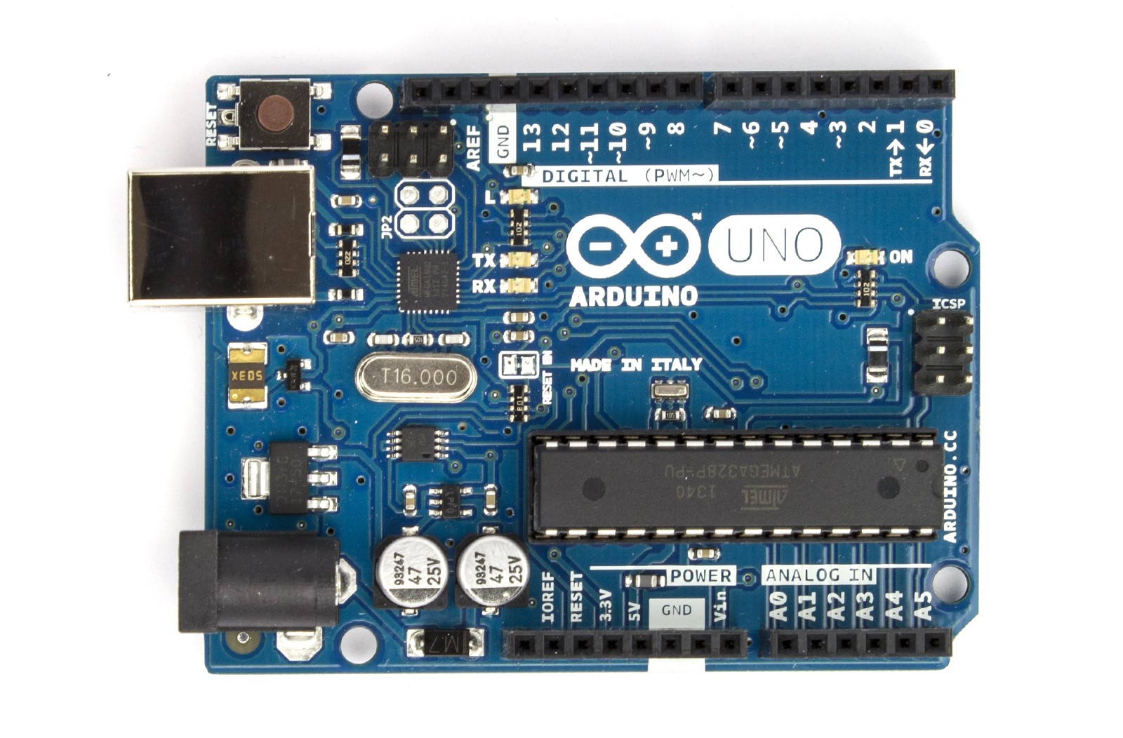 Arduino Uno
16. Conclusion: Unleash Your Car’s Potential with DIY Diagnostics
Connecting an Arduino to your car’s OBD2 port via WiFi opens up a world of possibilities for DIY diagnostics and customization. By following the steps outlined in this guide, you can gain valuable insights into your vehicle’s performance, create custom dashboards, and even integrate your car with your home automation system. While there may be challenges along the way, the rewards of this project are well worth the effort. So, gather your components, fire up your Arduino IDE, and start exploring the potential of your car’s data. And remember, MERCEDES-DIAGNOSTIC-TOOL.EDU.VN is here to support you with the latest tools, information, and expert guidance.
Ready to take your Mercedes-Benz diagnostics and customization to the next level? Contact MERCEDES-DIAGNOSTIC-TOOL.EDU.VN today for expert advice on selecting the right diagnostic tools, unlocking hidden features, and performing essential repairs and maintenance. Reach out to us at 789 Oak Avenue, Miami, FL 33101, United States, Whatsapp: +1 (641) 206-8880, or visit our website at MERCEDES-DIAGNOSTIC-TOOL.EDU.VN. Let us help you unleash the full potential of your Mercedes-Benz.