This guide by MERCEDES-DIAGNOSTIC-TOOL.EDU.VN provides comprehensive instructions on how to make an OBD2 to USB cable at home, offering a cost-effective diagnostic tool solution for Mercedes-Benz owners and automotive enthusiasts. By following these steps, you will gain the ability to connect your Mercedes to diagnostic software, read error codes, and potentially unlock hidden features, all while saving money on professional diagnostic services. Unlock your Mercedes-Benz diagnostic potential with this DIY guide and explore vehicle diagnostics, automotive customization, and DIY car repair.
Contents
- 1. Understanding the Basics of OBD2 to USB Cables
- 1.1. What is the OBD2 Protocol?
- 1.2. Why Make Your Own Cable?
- 1.3. Common Uses of an OBD2 to USB Cable
- 2. Identifying Your Intentions
- 2.1. Basic Error Code Reading and Resetting
- 2.2. Advanced Diagnostics and Data Monitoring
- 2.3. Unlocking Hidden Features and Customization
- 2.4. Cost-Effective DIY Car Repairs
- 2.5. Educational Purposes and Automotive Learning
- 3. Essential Tools and Components
- 3.1. Tools Required
- **3.2. Components Needed
- 3.3. Component Considerations
- 4. Step-by-Step Guide to Making the Cable
- 4.1. Preparing the OBD-II Cable
- 4.2. Preparing the 4-Pin Connector
- 4.3. Attaching Pins to the 4-Pin Connector
- 4.4. Assembling the 4-Pin Connector
- 5. Connecting to a USB Adapter
- 5.1. Choosing the Right USB Adapter
- 5.2. Wiring the USB Adapter
- 6. Testing Your Homemade Cable
- 6.1. Continuity Testing
- 6.2. Voltage Testing
- 6.3. Software Compatibility
- 7. Choosing the Right Diagnostic Software
- 7.1. Free Diagnostic Software
- 7.2. Paid Diagnostic Software
- 7.3. Software Features to Consider
- 8. Safety Precautions and Troubleshooting Tips
- 8.1. Safety Precautions
- 8.2. Troubleshooting Tips
- 9. Advanced Projects and Customizations
- 9.1. Adding Support for Additional Protocols
- 9.2. Creating a Wireless OBD2 Adapter
- 9.3. Building a Custom Diagnostic Tool
- 10. Benefits of Using Information and Services from MERCEDES-DIAGNOSTIC-TOOL.EDU.VN
- 10.1. Comprehensive Diagnostic Information
- 10.2. Step-by-Step Guides for Unlocking Hidden Features
- 10.3. Expert Guidance on Repairs and Maintenance
- 10.4. Cost-Effective Solutions
- 10.5. Peace of Mind
- 11. FAQ: Homemade OBD2 To USB Cable
- 11.1. What is the best USB adapter for an OBD2 cable?
- 11.2. Can I use any OBD2 software with my homemade cable?
- 11.3. Is it safe to make my own OBD2 cable?
- 11.4. What if my car is not communicating with the cable?
- 11.5. How do I know which pins to connect?
- 11.6. What gauge wire should I use?
- 11.7. Do I need a special crimping tool?
- 11.8. Where can I find drivers for my USB adapter?
- 11.9. Can I damage my car’s ECU with a homemade cable?
- 11.10. How do I test my cable after building it?
1. Understanding the Basics of OBD2 to USB Cables
What is an OBD2 to USB cable, and why would you want to make one yourself? An OBD2 (On-Board Diagnostics II) to USB cable allows you to connect your car’s diagnostic port to a computer. This connection enables you to read diagnostic trouble codes (DTCs), monitor real-time data, and perform various diagnostic tests using specialized software.
1.1. What is the OBD2 Protocol?
OBD2, or On-Board Diagnostics II, is a standardized system used in most cars and light trucks manufactured after 1996. Its primary function is to monitor the performance of the engine and emissions control systems. When a problem is detected, the OBD2 system generates a diagnostic trouble code (DTC) that can be accessed using diagnostic tools. The OBD2 port, typically located under the dashboard, provides access to this information. According to the Environmental Protection Agency (EPA), OBD2 was mandated to ensure vehicles meet emissions standards and to provide technicians with a standardized way to diagnose issues.
1.2. Why Make Your Own Cable?
Making your own OBD2 to USB cable can save you money compared to buying a pre-made one. It also gives you the flexibility to customize the cable to your specific needs. Furthermore, it’s a great learning experience that can deepen your understanding of automotive diagnostics. A study by the National Institute for Automotive Service Excellence (ASE) highlights the importance of DIY car repairs for both cost savings and educational purposes.
1.3. Common Uses of an OBD2 to USB Cable
- Reading Diagnostic Trouble Codes (DTCs): Identify why your check engine light is on.
- Clearing DTCs: Reset the check engine light after repairs.
- Monitoring Real-Time Data: View engine parameters like RPM, temperature, and sensor readings.
- Performing Diagnostic Tests: Run tests on specific components like O2 sensors or fuel injectors.
- Customizing Vehicle Settings: Some software allows you to modify vehicle settings and unlock hidden features.
2. Identifying Your Intentions
Understanding what you want to achieve with your homemade OBD2 to USB cable is essential for tailoring the process to your specific needs. Here are five common intentions behind creating such a cable, each requiring a slightly different approach and level of expertise.
2.1. Basic Error Code Reading and Resetting
Many users aim to create an OBD2 to USB cable simply to read and reset diagnostic trouble codes (DTCs). This allows them to understand why their check engine light is on and clear it after addressing the underlying issue.
2.2. Advanced Diagnostics and Data Monitoring
Some users require more advanced diagnostic capabilities, such as monitoring real-time sensor data (e.g., RPM, temperature, and O2 sensor readings) and performing specific diagnostic tests. This level of diagnostics often requires more sophisticated software and a reliable cable connection.
2.3. Unlocking Hidden Features and Customization
Enthusiasts may want to use an OBD2 to USB cable to unlock hidden features or customize vehicle settings, such as adjusting lighting parameters or enabling specific functions. This often involves using specialized software and understanding the vehicle’s electronic control unit (ECU).
2.4. Cost-Effective DIY Car Repairs
Creating an OBD2 to USB cable can be a cost-effective way to perform DIY car repairs. By accurately diagnosing issues and monitoring repairs, users can save money on professional mechanic fees. According to a survey by the American Automobile Association (AAA), DIY car repairs can save vehicle owners an average of $500 per year.
2.5. Educational Purposes and Automotive Learning
For some, the process of making an OBD2 to USB cable is primarily for educational purposes. It provides a hands-on learning experience in automotive diagnostics and electronics, fostering a deeper understanding of vehicle systems. A study by the National Center for Automotive Science and Technology (NCAT) emphasizes the importance of practical learning in automotive education.
3. Essential Tools and Components
Before you start building your OBD2 to USB cable, you need to gather the necessary tools and components. Having everything on hand will make the process smoother and more efficient.
3.1. Tools Required
- Wire Strippers/Cutters: For stripping insulation from wires and cutting wires to the desired length.
- Needle-Nose Pliers: For gripping and manipulating small components.
- Soldering Iron (Recommended): For creating secure and reliable connections between wires and pins.
- Multimeter (Recommended): For testing continuity and voltage to ensure proper connections.
- Molex Crimping Tool (Optional): For crimping pins onto wires (can be substituted with pliers, but a crimping tool provides a more secure connection).
**3.2. Components Needed
| Component | Description | Where to Buy |
|---|---|---|
| 4-Pin Connector | Connects to the USB adapter or diagnostic interface. Pin/wire size = 22-16AWG; insulation/seal size = 1.3-1.7mm. | Corsa Technic, electronics suppliers |
| OBD-II Cable | Connects to the vehicle’s OBD2 port. | Corsa Technic, automotive parts stores, online retailers |
| USB to Serial Adapter (FTDI) | Converts USB signal to serial for communication with the OBD2 port. Ensure it supports the necessary protocols (e.g., CAN, ISO). | Amazon, eBay, electronics suppliers |
| Wires | For connecting the OBD2 connector to the 4-pin connector. Recommended wire size is 22-16AWG. | Automotive parts stores, electronics suppliers |
| Heat Shrink Tubing | For insulating and protecting soldered connections. | Automotive parts stores, electronics suppliers |
| Resistors (Optional) | May be needed for specific diagnostic protocols. Check your diagnostic software requirements. | Electronics suppliers |
| Electrical Tape | For additional insulation and securing wires. | Automotive parts stores, hardware stores |
| Connector Housing | The plastic part that holds all of the pins and is a connector for use with other devices. | Online retailers |
3.3. Component Considerations
- USB to Serial Adapter: An FTDI-based adapter is generally recommended for its reliability and compatibility with various diagnostic software. Ensure the adapter supports the necessary communication protocols for your vehicle (e.g., CAN, ISO).
- OBD-II Cable: You can either purchase a complete OBD-II cable or just the female connector if you have spare wire. If buying only the connector, ensure you know the wire size to match the appropriate 4-pin connector.
- Wires: Use good-quality wires of the appropriate gauge (22-16AWG) to ensure reliable connections.
4. Step-by-Step Guide to Making the Cable
Follow these detailed steps to assemble your OBD2 to USB cable.
4.1. Preparing the OBD-II Cable
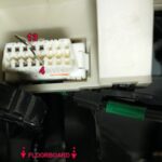
1: Identify the Wires:
Of the 16 pins on the OBD-II connector, only four are essential for basic diagnostics:
- Pin 4: Chassis Ground
- Pin 6: CAN High (J-2284)
- Pin 14: CAN Low (J-2284)
- Pin 16: Battery Power
2: Strip the Sheath:
Carefully remove the outer sheath and shielding from the OBD-II cable to expose the individual wires. A study by the Society of Automotive Engineers (SAE) emphasizes the importance of proper wire stripping techniques to avoid damaging the conductors.
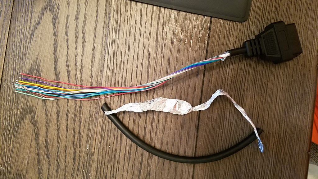 Stripped sheath and shielding
3: Separate the Wires:
Separate the four wires you will be using from the rest and set the remaining wires aside, securing them with a zip tie to keep them out of the way.
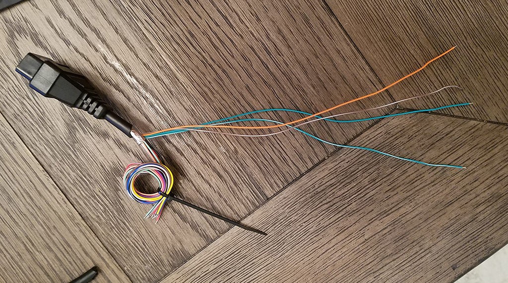 Separated 4 wires being used
4.2. Preparing the 4-Pin Connector
1: Strip the Wire Ends:
Strip about 3/8 inch of insulation from the ends of the four wires.
2: Thicken the Wires (if necessary):
If the wires from the OBD-II cable are thinner than the pins on the 4-pin connector (e.g., 26AWG wire with 22AWG pins), fold the exposed wire over on itself and twist it to create a thicker wire that will fit more securely in the pin.
 Wire too small for pin connector
3: Slide on Rubber Seals:
Slide a rubber seal over each wire to provide insulation and prevent shorts.
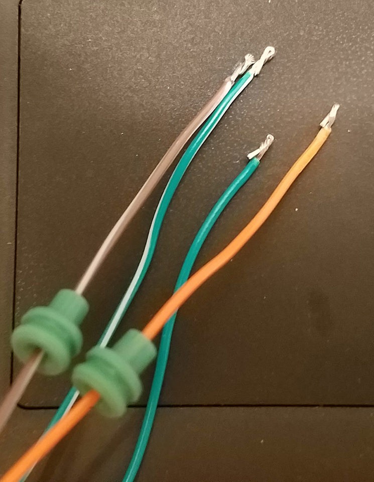 Rubber seals on wires
4.3. Attaching Pins to the 4-Pin Connector
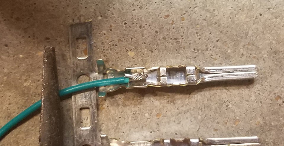
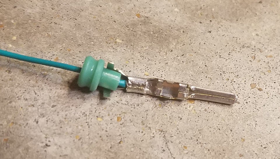
1: Solder the Wires to the Pins (Recommended):
Solder the wire to the pin connector to create a solid connection. This is especially important if the wire is thinner than the pin.
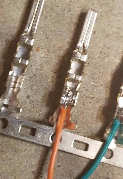 Soldering wire to pin connector
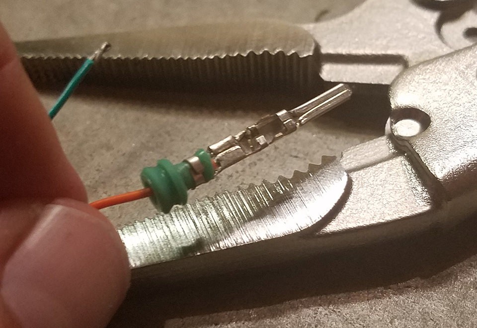
2: Crimp the Pins (Alternative):
If you have a Molex crimping tool, crimp the connector over the wire. If not, use needle-nose pliers to carefully fold the prongs over the wire, ensuring a tight connection.
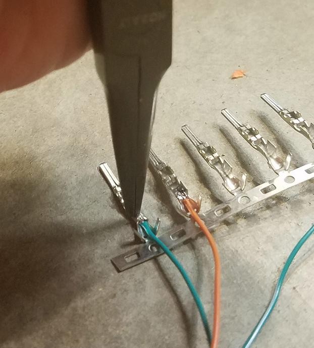 Crimping the connector over the wire
 Crimped connector over wire
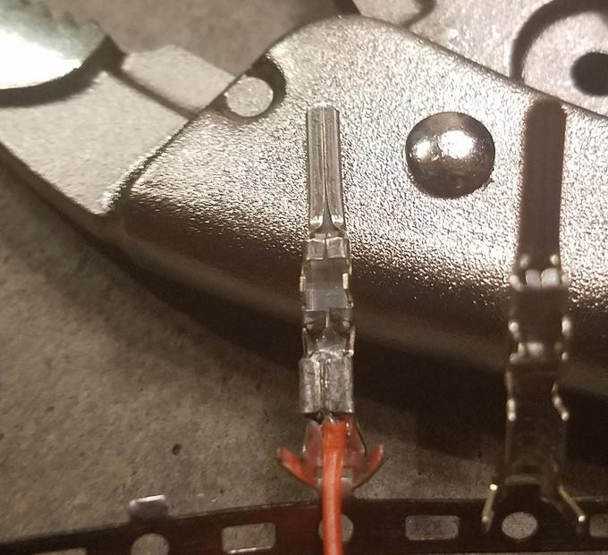
3: Secure the Rubber Seal:
Slide the rubber seal up to the back of the pin and use pliers to fold the prongs over the seal, securing it in place.
 Folding prongs over rubber seal
 Prongs folded over seal
 Seal secured with prongs
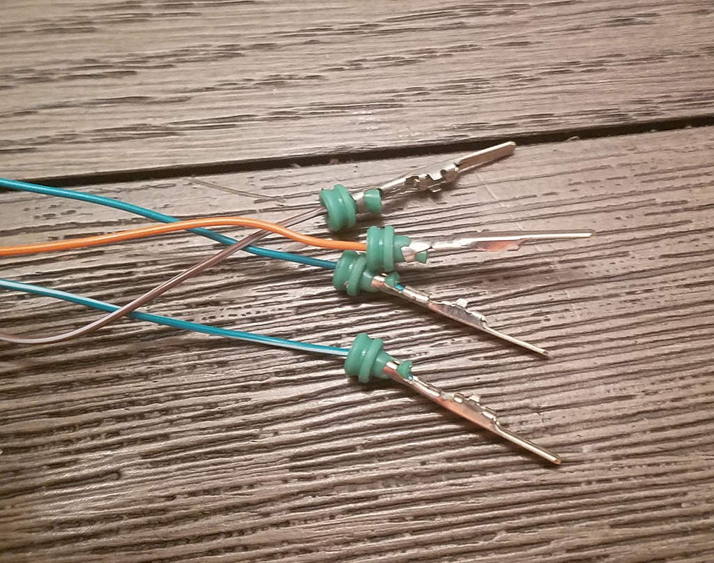
4.4. Assembling the 4-Pin Connector
1: Twist the Wire Pairs:
Pair off the wires and twist them together to reduce interference. The recommended pairs are:
- Pin 4 (Chassis Ground) / Pin 16 (Battery Power)
- Pin 6 (CAN High) / Pin 14 (CAN Low)
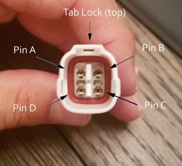
2: Insert Pins into the Connector:
Insert the pins into the 4-pin connector in the following orientation:
- Pin 14 (CAN Low) > Connector Slot A
- Pin 6 (CAN High) > Connector Slot B
- Pin 16 (Battery Power) > Connector Slot C
- Pin 4 (Chassis Ground) > Connector Slot D
Ensure the pins lock into place with an audible click.
 Inserting pins into the 4-pin connector
5. Connecting to a USB Adapter
To connect your homemade OBD2 cable to a computer, you will need a USB adapter. The most common type is a USB to serial adapter, which converts the USB signal to a serial signal that can be understood by the OBD2 port.
5.1. Choosing the Right USB Adapter
- FTDI Chip: Look for adapters that use an FTDI (Future Technology Devices International) chip. FTDI chips are known for their reliability and compatibility with various operating systems and diagnostic software.
- Supported Protocols: Ensure the adapter supports the communication protocols used by your vehicle, such as CAN (Controller Area Network), ISO 9141, and KWP2000.
- Driver Availability: Check that drivers are readily available for your operating system (Windows, macOS, Linux).
5.2. Wiring the USB Adapter
1: Identify the Necessary Pins:
The USB to serial adapter will have several pins, but you only need to connect a few to your 4-pin connector. Typically, you will need to connect:
- Ground (GND): Connect to Pin 4 (Chassis Ground) of the OBD2 connector.
- Transmit (TX): Connect to Pin 6 (CAN High) of the OBD2 connector.
- Receive (RX): Connect to Pin 14 (CAN Low) of the OBD2 connector.
- Power (VCC or 5V): Connect to Pin 16 (Battery Power) of the OBD2 connector.
2: Connect the Wires:
Use the same soldering or crimping techniques as before to connect the wires from the USB adapter to the corresponding pins on your 4-pin connector.
3: Insulate the Connections:
Use heat shrink tubing or electrical tape to insulate the connections and prevent shorts.
6. Testing Your Homemade Cable
After assembling your OBD2 to USB cable, it’s crucial to test its functionality before using it for critical diagnostics.
6.1. Continuity Testing
Use a multimeter to perform a continuity test between the OBD2 connector pins and the corresponding pins on the USB adapter or 4-pin connector. This ensures that the connections are solid and there are no breaks in the wiring.
6.2. Voltage Testing
With the cable connected to your vehicle’s OBD2 port, use a multimeter to check the voltage on Pin 16 (Battery Power). You should see a reading close to your vehicle’s battery voltage (typically around 12V).
6.3. Software Compatibility
Connect the cable to your computer and install the necessary drivers for the USB adapter. Then, launch your diagnostic software and attempt to connect to your vehicle. If the software recognizes the cable and can communicate with your vehicle’s ECU, your cable is working correctly.
7. Choosing the Right Diagnostic Software
Selecting the appropriate diagnostic software is crucial for effectively using your homemade OBD2 to USB cable. The software you choose will depend on your specific needs, whether it’s basic error code reading or advanced data monitoring and customization.
7.1. Free Diagnostic Software
- OBD Auto Doctor: A popular free software that allows you to read and clear diagnostic trouble codes, monitor real-time data, and perform basic diagnostic tests.
- ScanTool.net: Offers a free version of their ScanTool software with similar features to OBD Auto Doctor.
- Torque Lite (Android): A free version of the Torque app for Android devices, which connects to your vehicle via Bluetooth or USB.
7.2. Paid Diagnostic Software
- VCDS (VAG-COM Diagnostic System): A comprehensive diagnostic software specifically designed for Volkswagen, Audi, SEAT, and Skoda vehicles. It offers advanced features like module coding, adaptation, and guided fault finding. According to Ross-Tech, the developers of VCDS, it is used by professional mechanics and DIY enthusiasts alike.
- FORScan: A powerful diagnostic software for Ford, Lincoln, and Mercury vehicles. It provides access to advanced features like module programming, parameter resets, and bi-directional control. FORScan is highly regarded for its ability to access manufacturer-specific diagnostic data.
- BMW ISTA: The official diagnostic software used by BMW dealerships. It offers comprehensive diagnostic and programming capabilities for BMW vehicles. However, it can be expensive and require specialized knowledge to use effectively.
- Mercedes XENTRY/DAS: The official diagnostic software used by Mercedes-Benz dealerships. Similar to BMW ISTA, it provides extensive diagnostic and programming features for Mercedes vehicles but is typically more suitable for professional use.
7.3. Software Features to Consider
- Compatibility: Ensure the software is compatible with your vehicle’s make and model.
- Features: Choose software that offers the features you need, such as error code reading, data monitoring, module coding, and bi-directional control.
- User Interface: Look for software with a user-friendly interface that is easy to navigate and understand.
- Updates: Check if the software is regularly updated to support new vehicles and features.
- Support: Consider the availability of technical support and online resources.
8. Safety Precautions and Troubleshooting Tips
Working with automotive electronics can be risky if proper precautions are not taken. Here are some essential safety tips and troubleshooting advice to keep you safe and ensure your homemade OBD2 to USB cable works correctly.
8.1. Safety Precautions
- Disconnect the Battery: Before working on any electrical components, disconnect the negative terminal of your vehicle’s battery to prevent shorts and electrical damage.
- Use Proper Tools: Use insulated tools to avoid electrical shocks.
- Avoid Working in Wet Conditions: Never work on electrical systems in wet or damp environments.
- Double-Check Connections: Always double-check your wiring connections before connecting the cable to your vehicle or computer.
- Follow Software Instructions: Carefully follow the instructions provided by your diagnostic software to avoid damaging your vehicle’s ECU.
8.2. Troubleshooting Tips
- Cable Not Recognized: If your computer does not recognize the USB adapter, ensure that the drivers are properly installed. Try a different USB port or reinstall the drivers.
- Communication Errors: If the diagnostic software cannot communicate with your vehicle’s ECU, check the wiring connections and ensure that the USB adapter supports the necessary communication protocols.
- Error Codes Not Displaying: If you are not seeing any error codes, make sure that your vehicle’s ignition is turned on and that the diagnostic software is properly configured.
- Intermittent Connection: If you are experiencing an intermittent connection, check the wiring for loose connections or damaged wires.
9. Advanced Projects and Customizations
Once you have successfully built a basic OBD2 to USB cable, you can explore more advanced projects and customizations to enhance your diagnostic capabilities.
9.1. Adding Support for Additional Protocols
Some vehicles may use communication protocols that are not supported by standard OBD2 adapters. You can add support for these protocols by incorporating additional circuitry into your homemade cable.
9.2. Creating a Wireless OBD2 Adapter
You can create a wireless OBD2 adapter by connecting a Bluetooth module to your cable. This allows you to connect to your vehicle wirelessly using a smartphone or tablet.
9.3. Building a Custom Diagnostic Tool
With a solid understanding of OBD2 protocols and automotive electronics, you can build your own custom diagnostic tool using a microcontroller and a display screen. This allows you to create a personalized diagnostic solution tailored to your specific needs.
10. Benefits of Using Information and Services from MERCEDES-DIAGNOSTIC-TOOL.EDU.VN
While building your own OBD2 to USB cable is a rewarding project, accessing professional information and services can significantly enhance your diagnostic capabilities and ensure the safety and reliability of your vehicle.
10.1. Comprehensive Diagnostic Information
MERCEDES-DIAGNOSTIC-TOOL.EDU.VN provides detailed information on Mercedes-Benz diagnostic tools, including their features, capabilities, and compatibility with different models. This information can help you make informed decisions about the tools and software you need for your specific vehicle.
10.2. Step-by-Step Guides for Unlocking Hidden Features
Unlock the full potential of your Mercedes-Benz with our step-by-step guides on accessing and enabling hidden features. From activating ambient lighting to customizing driving modes, we provide clear, easy-to-follow instructions.
10.3. Expert Guidance on Repairs and Maintenance
Our team of experienced Mercedes-Benz technicians offers expert guidance on repairs and maintenance, ensuring your vehicle receives the best possible care. Benefit from our in-depth knowledge and keep your Mercedes-Benz running smoothly.
10.4. Cost-Effective Solutions
By utilizing the information and services from MERCEDES-DIAGNOSTIC-TOOL.EDU.VN, you can save money on professional diagnostic services and repairs. Our resources empower you to diagnose and fix common issues yourself, reducing the need for expensive trips to the dealership.
10.5. Peace of Mind
With access to reliable information and expert guidance, you can have peace of mind knowing that you are making informed decisions about your vehicle’s care. Trust MERCEDES-DIAGNOSTIC-TOOL.EDU.VN to provide the resources you need to keep your Mercedes-Benz in top condition.
11. FAQ: Homemade OBD2 To USB Cable
Have questions about creating your own OBD2 to USB cable? Here are some frequently asked questions to guide you.
11.1. What is the best USB adapter for an OBD2 cable?
An FTDI-based USB to serial adapter is generally recommended for its reliability and compatibility.
11.2. Can I use any OBD2 software with my homemade cable?
Not all software is compatible with homemade cables. Check the software’s compatibility requirements.
11.3. Is it safe to make my own OBD2 cable?
Yes, if you follow safety precautions and double-check your connections.
11.4. What if my car is not communicating with the cable?
Check the wiring, USB adapter drivers, and software settings.
11.5. How do I know which pins to connect?
Refer to the OBD2 pinout diagram and the USB adapter documentation.
11.6. What gauge wire should I use?
22-16AWG wire is recommended for connecting the OBD2 connector to the 4-pin connector.
11.7. Do I need a special crimping tool?
A Molex crimping tool is recommended but not required; pliers can be used as a substitute.
11.8. Where can I find drivers for my USB adapter?
Drivers can usually be found on the manufacturer’s website or included with the adapter.
11.9. Can I damage my car’s ECU with a homemade cable?
Yes, if the cable is not properly constructed or if the software is used incorrectly. Follow safety precautions.
11.10. How do I test my cable after building it?
Use a multimeter to check continuity and voltage, and test with diagnostic software.
By following this comprehensive guide, you can confidently create your own OBD2 to USB cable and unlock the diagnostic potential of your Mercedes-Benz. For further assistance and expert guidance, contact MERCEDES-DIAGNOSTIC-TOOL.EDU.VN at 789 Oak Avenue, Miami, FL 33101, United States, or via Whatsapp at +1 (641) 206-8880. Visit our website at MERCEDES-DIAGNOSTIC-TOOL.EDU.VN for more information.
Ready to unlock the full diagnostic potential of your Mercedes-Benz? Contact MERCEDES-DIAGNOSTIC-TOOL.EDU.VN today for expert guidance on selecting the right diagnostic tools and software, as well as step-by-step instructions on unlocking hidden features and performing essential repairs and maintenance. Reach out to us at 789 Oak Avenue, Miami, FL 33101, United States, via Whatsapp at +1 (641) 206-8880, or visit our website at MERCEDES-DIAGNOSTIC-TOOL.EDU.VN. Let us help you keep your Mercedes-Benz running smoothly and efficiently.