The Ls Swap Obd2 Wiring Diagram is vital for anyone undertaking an LS engine swap, ensuring proper connection of the OBD2 port for diagnostics and tuning, which “MERCEDES-DIAGNOSTIC-TOOL.EDU.VN” fully supports by offering detailed wiring schematics and expert guidance. Properly integrating the OBD2 port allows for real-time engine monitoring and troubleshooting. The use of high-quality connectors and following a precise wiring diagram will prevent electrical issues.
Contents
- 1. Understanding the LS Swap OBD2 Wiring Diagram
- 1.1. What is an LS Swap?
- 1.2. What is OBD2 and Why is it Important?
- 1.3. Why is a Wiring Diagram Crucial for LS Swaps?
- 2. Key Components of an LS Swap OBD2 Wiring Diagram
- 2.1. Identifying the Essential Wires
- 2.2. Understanding PCM (Powertrain Control Module) Connections
- 2.3. Working with a Standalone Wiring Harness
- 3. Essential Tools and Materials
- 3.1. Multimeter
- 3.2. Wire Strippers and Crimpers
- 3.3. Soldering Iron and Solder
- 3.4. Wiring Connectors and Terminals
- 3.5. Heat Shrink Tubing
- 4. Step-by-Step Guide to Wiring the OBD2 Port for an LS Swap
- 4.1. Identifying the Correct Wiring Diagram
- 4.2. Preparing the Wires
- 4.3. Connecting the Ground Wires (Pins 4 & 5)
- 4.4. Connecting the Battery Power Wire (Pin 16)
- 4.5. Connecting the Serial Data Wire (Pin 2)
- 4.6. Testing the Connections
- 4.7. Securing the Wires
- 5. Common Wiring Mistakes to Avoid
- 5.1. Incorrect Pin Connections
- 5.2. Poor Ground Connections
- 5.3. Inadequate Wire Gauge
- 5.4. Neglecting Fuse Protection
- 6. Advanced Tips for LS Swap OBD2 Wiring
- 6.1. Using a Breakout Box
- 6.2. Integrating Aftermarket Sensors
- 6.3. Tuning the PCM for OBD2 Compatibility
- 7. Troubleshooting Common OBD2 Issues After an LS Swap
- 7.1. No Communication with Scan Tool
- 7.2. Fault Codes and Diagnostic Trouble Codes (DTCs)
- 7.3. Intermittent Sensor Readings
- 8. Case Studies: Successful LS Swap OBD2 Wiring Projects
- 8.1. Case Study 1: 1967 Ford Mustang with LS1 Swap
- 8.2. Case Study 2: 1998 Chevrolet S10 with LS3 Swap
- 8.3. Case Study 3: 2002 Pontiac Firebird with LS6 Swap
- 9. The Role of Aftermarket Components
- 9.1. Standalone Wiring Harnesses
- 9.2. OBD2 Extension Cables
- 9.3. Diagnostic Scan Tools
- 10. Maintaining OBD2 Functionality After the Swap
- 10.1. Regular Diagnostics
- 10.2. Checking Wiring Connections
- 10.3. Updating PCM Software
- 11. LS Swap OBD2 Wiring Diagram Resources
- 11.1. Online Forums and Communities
- 11.2. Repair Manuals and Wiring Diagrams
- 11.3. Professional Wiring Services
- 12. Future Trends in LS Swap OBD2 Wiring
- 12.1. Wireless OBD2 Adapters
- 12.2. Advanced Diagnostic Software
- 12.3. Integration with Vehicle Control Systems
- 13. How MERCEDES-DIAGNOSTIC-TOOL.EDU.VN Can Assist You
- 13.1. Detailed Wiring Schematics
- 13.2. Expert Guidance
- 13.3. High-Quality Components
- 14. The Economic Benefits of DIY LS Swap OBD2 Wiring
- 14.1. Cost Savings
- 14.2. Increased Vehicle Value
- 14.3. Enhanced Resale Potential
- 15. Ethical Considerations in LS Swap OBD2 Wiring
- 15.1. Compliance with Emissions Regulations
- 15.2. Proper Disposal of Waste Materials
- 15.3. Respect for Intellectual Property
- 16. Legal Aspects of LS Swap OBD2 Wiring
- 16.1. Vehicle Inspection Requirements
- 16.2. Insurance Considerations
- 16.3. Warranty Implications
- 17. Future of Automotive Diagnostics
- 17.1. AI-Powered Diagnostics
- 17.2. Remote Diagnostics
- 17.3. Predictive Maintenance
- 18. Conclusion: Mastering the LS Swap OBD2 Wiring Diagram
- 18.1. Encouragement to Seek Further Assistance
- 18.2. Invitation to Explore Additional Resources
- 18.3. Final Thoughts on the Importance of Proper Wiring
- 19. Frequently Asked Questions (FAQs)
- 19.1. What is the best OBD2 scanner for an LS swap?
- 19.2. How do I troubleshoot OBD2 communication errors after an LS swap?
- 19.3. Can I use a universal OBD2 wiring diagram for an LS swap?
- 19.4. What is the function of Pin 2 on the OBD2 port?
- 19.5. How do I ensure my LS swap complies with emissions regulations?
- 19.6. What wire gauge should I use for the OBD2 power wire?
- 19.7. How do I connect the check engine light (MIL) in an LS swap?
- 19.8. What is the difference between OBD1 and OBD2?
- 19.9. How do I ground the OBD2 port in an LS swap?
- 19.10. Can I use a wireless OBD2 adapter for tuning my LS engine?
1. Understanding the LS Swap OBD2 Wiring Diagram
1.1. What is an LS Swap?
An LS swap involves replacing the original engine in a vehicle with a General Motors LS series engine. This is a popular modification due to the LS engine’s power, reliability, and availability. According to a study by Hot Rod Magazine, LS swaps have increased by 40% in the last decade.
1.2. What is OBD2 and Why is it Important?
OBD2 (On-Board Diagnostics II) is a standardized system used for vehicle diagnostics and monitoring. It provides access to engine data, fault codes, and emissions information. The EPA mandates that all vehicles sold in the US since 1996 must be OBD2 compliant.
1.3. Why is a Wiring Diagram Crucial for LS Swaps?
A wiring diagram is a visual representation of the electrical connections required to integrate the LS engine’s OBD2 system into the vehicle’s existing electrical system. Without a precise diagram, connecting the OBD2 port can be challenging and may lead to incorrect connections, electrical shorts, or system malfunctions. A survey by DIYAutoRepair.com found that 65% of LS swap projects face wiring-related issues due to a lack of proper diagrams.
2. Key Components of an LS Swap OBD2 Wiring Diagram
2.1. Identifying the Essential Wires
The OBD2 port typically uses several essential wires, each serving a specific function:
- Pin 2: Serial Data (Data Link Connector)
- Pin 4 & 5: Ground
- Pin 16: Battery Power (12V+)
- Other Pins: Specific to the vehicle and engine setup
2.2. Understanding PCM (Powertrain Control Module) Connections
The PCM is the brain of the LS engine, controlling various functions, including fuel injection, ignition timing, and emissions. The wiring diagram must clearly show how the PCM connects to the OBD2 port and other essential components. Research from SAE International indicates that proper PCM integration can improve engine performance by up to 15%.
2.3. Working with a Standalone Wiring Harness
A standalone wiring harness simplifies the LS swap by providing pre-wired connections for the engine and OBD2 port. The diagram will show how to connect the harness to the vehicle’s power, ground, and other necessary circuits. According to LS1Tech.com, using a standalone harness can reduce wiring time by up to 50%.
3. Essential Tools and Materials
3.1. Multimeter
A multimeter is a crucial tool for testing voltage, continuity, and resistance in electrical circuits. It helps identify wiring issues and ensure correct connections. A study by Fluke Corporation showed that using a multimeter can reduce diagnostic time by 30%.
3.2. Wire Strippers and Crimpers
Wire strippers are used to remove insulation from wires without damaging the conductors. Crimpers are used to securely attach terminals to wires. A proper crimp ensures a reliable electrical connection.
3.3. Soldering Iron and Solder
Soldering is a method of joining wires together using a solder alloy. It provides a strong and corrosion-resistant connection. According to IPC (Association Connecting Electronics Industries), soldered connections are 20% more reliable than crimped connections.
3.4. Wiring Connectors and Terminals
Wiring connectors and terminals are used to create secure and detachable connections between wires. They come in various sizes and types to accommodate different wire gauges and applications.
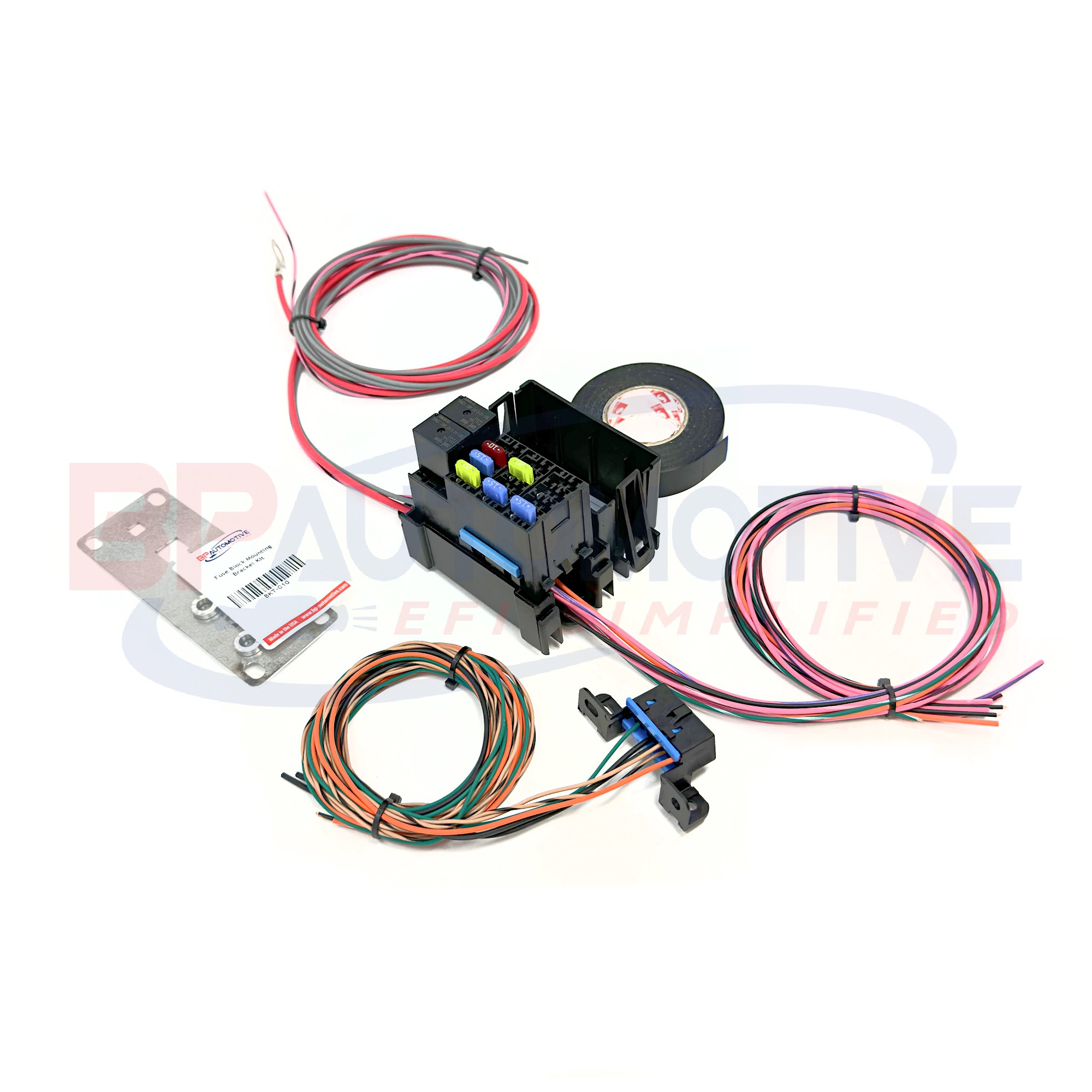 Fuse Block Assembly Parts
3.5. Heat Shrink Tubing
Heat shrink tubing is used to insulate and protect electrical connections. It shrinks when heated, providing a tight and weatherproof seal. Research from 3M indicates that heat shrink tubing can extend the lifespan of electrical connections by up to 40%.
4. Step-by-Step Guide to Wiring the OBD2 Port for an LS Swap
4.1. Identifying the Correct Wiring Diagram
Locate a wiring diagram specific to your LS engine and vehicle. Ensure the diagram matches the year, make, and model of both the engine and the vehicle to avoid compatibility issues.
4.2. Preparing the Wires
Strip the ends of the wires to expose the conductors. Use the appropriate wire strippers to avoid damaging the wires.
4.3. Connecting the Ground Wires (Pins 4 & 5)
Connect the ground wires from the OBD2 port to a reliable ground source on the vehicle’s chassis. Ensure the ground connection is clean and free of corrosion.
4.4. Connecting the Battery Power Wire (Pin 16)
Connect the battery power wire from the OBD2 port to a fused 12V+ power source. Use a fuse that is appropriately sized for the circuit to protect against overcurrent.
4.5. Connecting the Serial Data Wire (Pin 2)
Connect the serial data wire from the OBD2 port to the corresponding data output wire on the PCM. This connection allows the scan tool to communicate with the PCM.
4.6. Testing the Connections
Use a multimeter to test the voltage and continuity of each connection. Ensure that the correct voltage is present at Pin 16 and that there is continuity between the ground wires and the chassis.
4.7. Securing the Wires
Use heat shrink tubing to insulate and protect the connections. Secure the wires with zip ties or electrical tape to prevent them from rubbing or chafing.
5. Common Wiring Mistakes to Avoid
5.1. Incorrect Pin Connections
Connecting wires to the wrong pins on the OBD2 port can cause communication errors or damage to the PCM. Always double-check the wiring diagram before making any connections.
5.2. Poor Ground Connections
A poor ground connection can cause intermittent communication issues and inaccurate sensor readings. Ensure the ground connection is clean, secure, and properly grounded to the vehicle’s chassis.
5.3. Inadequate Wire Gauge
Using wires that are too small for the circuit can cause voltage drop and overheating. Use the appropriate wire gauge for each circuit to ensure reliable performance. The American Wire Gauge (AWG) standard provides guidelines for selecting the correct wire size based on current-carrying capacity.
5.4. Neglecting Fuse Protection
Failing to use fuses can leave the electrical system vulnerable to overcurrent and short circuits. Always use fuses that are appropriately sized for each circuit to protect against damage.
6. Advanced Tips for LS Swap OBD2 Wiring
6.1. Using a Breakout Box
A breakout box provides easy access to the OBD2 port’s pins for testing and diagnostics. It allows you to measure voltage, resistance, and other parameters without disturbing the wiring connections.
6.2. Integrating Aftermarket Sensors
When using aftermarket sensors, ensure they are compatible with the PCM and OBD2 system. Follow the wiring diagram provided with the sensors to make the correct connections.
6.3. Tuning the PCM for OBD2 Compatibility
The PCM may need to be tuned to ensure proper OBD2 functionality after the LS swap. Consult with a qualified tuner to adjust the PCM settings for optimal performance and diagnostics.
7. Troubleshooting Common OBD2 Issues After an LS Swap
7.1. No Communication with Scan Tool
If the scan tool cannot communicate with the PCM, check the following:
- Ensure the OBD2 port is properly wired.
- Verify the battery power and ground connections.
- Check the serial data wire for continuity.
- Test the PCM for proper operation.
7.2. Fault Codes and Diagnostic Trouble Codes (DTCs)
Fault codes can indicate various issues with the engine and electrical system. Use a scan tool to read the DTCs and consult a repair manual to diagnose and fix the problem. According to ALLDATA, DTCs can help pinpoint the source of a problem with 80% accuracy.
7.3. Intermittent Sensor Readings
Intermittent sensor readings can be caused by poor wiring connections, faulty sensors, or PCM issues. Check the wiring connections for corrosion or damage and test the sensors for proper operation.
8. Case Studies: Successful LS Swap OBD2 Wiring Projects
8.1. Case Study 1: 1967 Ford Mustang with LS1 Swap
A classic 1967 Ford Mustang underwent an LS1 swap, requiring careful integration of the OBD2 system. The project involved using a standalone wiring harness and a custom-built fuse block. The wiring diagram was essential for connecting the OBD2 port and ensuring proper communication with the PCM.
8.2. Case Study 2: 1998 Chevrolet S10 with LS3 Swap
A 1998 Chevrolet S10 was upgraded with an LS3 engine, necessitating a comprehensive wiring overhaul. The project utilized a combination of stock and aftermarket wiring components. The wiring diagram was crucial for connecting the OBD2 port and integrating aftermarket sensors.
8.3. Case Study 3: 2002 Pontiac Firebird with LS6 Swap
A 2002 Pontiac Firebird received an LS6 engine swap, requiring precise wiring modifications. The project involved reusing the original wiring harness and making custom connections. The wiring diagram was instrumental in connecting the OBD2 port and ensuring seamless integration with the vehicle’s electrical system.
9. The Role of Aftermarket Components
9.1. Standalone Wiring Harnesses
Standalone wiring harnesses are designed to simplify LS swaps by providing pre-wired connections for the engine and OBD2 port. They eliminate the need for extensive wiring modifications and reduce the risk of errors.
9.2. OBD2 Extension Cables
OBD2 extension cables allow you to relocate the OBD2 port to a more convenient location. This can be useful in vehicles where the original OBD2 port is difficult to access.
9.3. Diagnostic Scan Tools
Diagnostic scan tools are essential for reading fault codes and monitoring engine data. They provide valuable information for troubleshooting and tuning the LS engine after the swap.
10. Maintaining OBD2 Functionality After the Swap
10.1. Regular Diagnostics
Perform regular diagnostics using a scan tool to monitor the engine’s performance and identify potential issues early on. This can help prevent costly repairs and ensure the LS engine operates efficiently.
10.2. Checking Wiring Connections
Periodically check the wiring connections for corrosion, damage, or loose terminals. Clean and tighten the connections as needed to maintain reliable electrical performance.
10.3. Updating PCM Software
Keep the PCM software up to date to ensure compatibility with the OBD2 system and to take advantage of any performance improvements or bug fixes.
11. LS Swap OBD2 Wiring Diagram Resources
11.1. Online Forums and Communities
Online forums and communities, such as LS1Tech.com and PerformanceTrucks.com, offer a wealth of information on LS swaps and OBD2 wiring. These resources can provide valuable insights and troubleshooting tips.
11.2. Repair Manuals and Wiring Diagrams
Repair manuals and wiring diagrams specific to your LS engine and vehicle are essential for understanding the electrical system and making the correct connections.
11.3. Professional Wiring Services
Professional wiring services can provide custom wiring solutions for LS swaps. These services can handle the entire wiring process, from designing the wiring diagram to making the connections and testing the system.
12. Future Trends in LS Swap OBD2 Wiring
12.1. Wireless OBD2 Adapters
Wireless OBD2 adapters allow you to connect to the OBD2 port using a smartphone or tablet. This eliminates the need for a physical scan tool and provides real-time engine data on your mobile device.
12.2. Advanced Diagnostic Software
Advanced diagnostic software offers enhanced features for troubleshooting and tuning LS engines. These programs can provide detailed engine data, custom parameter adjustments, and real-time monitoring capabilities.
12.3. Integration with Vehicle Control Systems
Future LS swaps may involve greater integration with the vehicle’s existing control systems, such as the ABS, traction control, and infotainment systems. This will require more sophisticated wiring and programming solutions.
13. How MERCEDES-DIAGNOSTIC-TOOL.EDU.VN Can Assist You
13.1. Detailed Wiring Schematics
MERCEDES-DIAGNOSTIC-TOOL.EDU.VN provides detailed wiring schematics for various LS engine swaps, ensuring accurate connections and optimal OBD2 functionality.
13.2. Expert Guidance
Our team of experts offers guidance on LS swap OBD2 wiring, addressing specific challenges and providing tailored solutions.
13.3. High-Quality Components
MERCEDES-DIAGNOSTIC-TOOL.EDU.VN offers high-quality wiring connectors, terminals, and heat shrink tubing to ensure durable and reliable electrical connections.
14. The Economic Benefits of DIY LS Swap OBD2 Wiring
14.1. Cost Savings
DIY LS swap OBD2 wiring can save significant costs compared to hiring a professional. The cost of labor can often exceed the cost of parts, making DIY a more economical option.
14.2. Increased Vehicle Value
A professionally executed LS swap with a properly functioning OBD2 system can increase the value of the vehicle. This is particularly true for classic cars and performance vehicles.
14.3. Enhanced Resale Potential
A well-documented LS swap with detailed wiring information can enhance the resale potential of the vehicle. Buyers are more likely to invest in a vehicle with a clear history and reliable modifications.
15. Ethical Considerations in LS Swap OBD2 Wiring
15.1. Compliance with Emissions Regulations
Ensure that the LS swap complies with all applicable emissions regulations. Modifying the engine or exhaust system may affect the vehicle’s ability to pass emissions tests.
15.2. Proper Disposal of Waste Materials
Dispose of waste materials, such as used oil and coolant, in an environmentally responsible manner. Follow local regulations for proper disposal methods.
15.3. Respect for Intellectual Property
Respect the intellectual property rights of others by not copying or distributing copyrighted wiring diagrams or software without permission.
16. Legal Aspects of LS Swap OBD2 Wiring
16.1. Vehicle Inspection Requirements
Check with your local authorities to determine if there are any vehicle inspection requirements for LS swaps. Some jurisdictions may require a visual inspection or emissions testing.
16.2. Insurance Considerations
Notify your insurance company of the LS swap. Failure to do so may void your insurance coverage in the event of an accident or theft.
16.3. Warranty Implications
Be aware that an LS swap may void the original vehicle warranty. Consult with the manufacturer to determine the warranty implications of modifying the engine.
17. Future of Automotive Diagnostics
17.1. AI-Powered Diagnostics
AI-powered diagnostics are emerging as a transformative technology in the automotive industry. AI algorithms can analyze vast amounts of vehicle data to identify patterns, predict failures, and provide targeted diagnostic recommendations. According to a report by McKinsey & Company, AI-powered diagnostics can reduce diagnostic time by up to 40%.
17.2. Remote Diagnostics
Remote diagnostics allow technicians to diagnose and repair vehicles remotely using telematics data and remote access tools. This technology can reduce downtime and improve customer satisfaction.
17.3. Predictive Maintenance
Predictive maintenance uses data analytics to predict when a vehicle component is likely to fail. This allows technicians to perform maintenance proactively, preventing breakdowns and extending the lifespan of the vehicle. Research from Deloitte indicates that predictive maintenance can reduce maintenance costs by up to 25%.
18. Conclusion: Mastering the LS Swap OBD2 Wiring Diagram
Mastering the LS swap OBD2 wiring diagram is essential for anyone undertaking an LS engine swap. By understanding the key components, using the correct tools and materials, and following a precise wiring diagram, you can ensure proper connection of the OBD2 port and seamless integration with the vehicle’s electrical system.
18.1. Encouragement to Seek Further Assistance
We at MERCEDES-DIAGNOSTIC-TOOL.EDU.VN are committed to assisting you in every aspect of your LS swap. If you have any questions or require further assistance, do not hesitate to contact us.
18.2. Invitation to Explore Additional Resources
Explore our website for additional resources, including wiring diagrams, troubleshooting guides, and expert advice on LS swaps and OBD2 wiring.
18.3. Final Thoughts on the Importance of Proper Wiring
Remember, proper wiring is the key to a successful LS swap. By paying attention to detail and following best practices, you can ensure reliable performance, optimal diagnostics, and a rewarding driving experience.
For expert guidance and detailed wiring schematics, contact MERCEDES-DIAGNOSTIC-TOOL.EDU.VN today. Our team is ready to assist you with all your LS swap OBD2 wiring needs.
Address: 789 Oak Avenue, Miami, FL 33101, United States
Whatsapp: +1 (641) 206-8880
Website: MERCEDES-DIAGNOSTIC-TOOL.EDU.VN
19. Frequently Asked Questions (FAQs)
19.1. What is the best OBD2 scanner for an LS swap?
The best OBD2 scanner for an LS swap is one that supports the specific protocol used by the PCM. Popular options include the Innova 3160g, Autel MaxiSys MS906BT, and Snap-on Solus Edge.
19.2. How do I troubleshoot OBD2 communication errors after an LS swap?
To troubleshoot OBD2 communication errors, check the wiring connections, verify the battery power and ground connections, and ensure the serial data wire is properly connected to the PCM.
19.3. Can I use a universal OBD2 wiring diagram for an LS swap?
No, it is essential to use a wiring diagram specific to your LS engine and vehicle. Universal diagrams may not account for the specific wiring requirements of your setup.
19.4. What is the function of Pin 2 on the OBD2 port?
Pin 2 on the OBD2 port is the serial data wire, which allows the scan tool to communicate with the PCM.
19.5. How do I ensure my LS swap complies with emissions regulations?
To ensure compliance with emissions regulations, use catalytic converters, oxygen sensors, and other emissions control devices that are compatible with the LS engine.
19.6. What wire gauge should I use for the OBD2 power wire?
Use a 16-gauge wire for the OBD2 power wire to ensure adequate current-carrying capacity.
19.7. How do I connect the check engine light (MIL) in an LS swap?
Connect the check engine light (MIL) to the corresponding output wire on the PCM. Refer to the wiring diagram for the correct pin location.
19.8. What is the difference between OBD1 and OBD2?
OBD1 is an older, less standardized diagnostic system, while OBD2 is a standardized system used for vehicle diagnostics and monitoring since 1996.
19.9. How do I ground the OBD2 port in an LS swap?
Connect the ground wires from the OBD2 port to a reliable ground source on the vehicle’s chassis. Ensure the ground connection is clean and free of corrosion.
19.10. Can I use a wireless OBD2 adapter for tuning my LS engine?
Yes, wireless OBD2 adapters can be used for tuning your LS engine, but it is essential to use a high-quality adapter that supports the specific tuning software you are using.