The Obd2 Dlc, or Data Link Connector, is your vehicle’s diagnostic port, and troubleshooting issues with it is crucial for accessing valuable data about your car’s health; MERCEDES-DIAGNOSTIC-TOOL.EDU.VN offers expert guidance and tools to help you diagnose and resolve OBD2 DLC problems effectively. Understanding its function, common problems, and troubleshooting steps will empower you to maintain your Mercedes-Benz in top condition. Get personalized support and expert solutions by contacting us on Whatsapp at +1 (641) 206-8880 to unlock the full potential of your Mercedes-Benz diagnostics with the support of our diagnostic tools and services.
Contents
- 1. Understanding the OBD2 DLC (Data Link Connector)
- 1.1. What is OBD2?
- 1.2. Function of the OBD2 DLC
- 1.3. Location of the OBD2 DLC in Mercedes-Benz Vehicles
- 1.4. Standard Pinout of the OBD2 DLC
- 1.5. Why is the OBD2 DLC Important?
- 2. Common Problems with the OBD2 DLC
- 2.1. Physical Damage to the Connector
- 2.2. Blown Fuses
- 2.3. Wiring Issues
- 2.4. Grounding Problems
- 2.5. CAN Bus Issues
- 2.6. Software or Firmware Issues
- 3. Step-by-Step Troubleshooting Guide for the OBD2 DLC
- 3.1. Tools and Equipment Needed
- 3.2. Initial Inspection
- 3.3. Testing for Power and Ground
- 3.4. Checking the CAN Bus
- 3.5. Testing the K-Line and L-Line (ISO 9141-2)
- 3.6. Verifying Communication with a Diagnostic Tool
- 3.7. Advanced Troubleshooting Steps
- 3.8. Seeking Professional Help
- 4. Advanced Diagnostic Techniques for OBD2 DLC Issues
- 4.1. Using an Oscilloscope
- 4.2. CAN Bus Diagnostics
- 4.3. Using a Breakout Box
- 4.4. Performing a Network Scan
- 4.5. Checking for Short Circuits and Open Circuits
- 4.6. Using Freeze Frame Data
- 5. Preventing OBD2 DLC Problems
- 5.1. Regular Maintenance Checks
- 5.2. Proper Handling of Diagnostic Tools
- 5.3. Protecting the Connector from Environmental Factors
- 5.4. Regular Software Updates for Diagnostic Tools
- 5.5. Avoiding Aftermarket Accessories That Interfere with the OBD2 System
- 6. The Future of OBD2 Technology
- 6.1. Enhanced Diagnostic Capabilities
- 6.2. Integration with Telematics Systems
- 6.3. Cybersecurity Considerations
- 6.4. Wireless OBD2 Adapters
- 6.5. Standardized Diagnostic Protocols
- 7. Case Studies: Resolving OBD2 DLC Issues
- 7.1. Case Study 1: Physical Damage to the Connector
- 7.2. Case Study 2: Blown Fuse
- 7.3. Case Study 3: Wiring Issues
- 7.4. Case Study 4: Grounding Problems
- 8. Choosing the Right OBD2 Diagnostic Tool for Your Mercedes-Benz
- 8.1. Types of OBD2 Diagnostic Tools
1. Understanding the OBD2 DLC (Data Link Connector)
The OBD2 DLC, or Data Link Connector, serves as the primary interface for accessing your vehicle’s onboard diagnostic system. It’s a standardized 16-pin connector found in most modern vehicles, including Mercedes-Benz models, typically located under the dashboard on the driver’s side.
1.1. What is OBD2?
OBD2, or On-Board Diagnostics II, is a standardized system that provides access to various vehicle subsystems. According to the Environmental Protection Agency (EPA), all cars and light trucks manufactured after 1996 in the United States are required to have an OBD2 system. This system monitors the performance of the engine, transmission, and other components, and it can detect malfunctions that could affect emissions or vehicle performance.
1.2. Function of the OBD2 DLC
The OBD2 DLC allows technicians and car owners to connect diagnostic tools to the vehicle’s computer system. This connection enables reading diagnostic trouble codes (DTCs), viewing live data, performing tests, and reprogramming certain control modules. For example, you can use the OBD2 DLC to check why your check engine light is on and identify the specific issue, such as a faulty oxygen sensor or a loose gas cap.
1.3. Location of the OBD2 DLC in Mercedes-Benz Vehicles
In most Mercedes-Benz vehicles, the OBD2 DLC is located under the dashboard on the driver’s side. However, the exact location may vary slightly depending on the model and year. Refer to your vehicle’s owner’s manual for the precise location. The connector is usually easily accessible, allowing for quick and convenient connection of diagnostic tools.
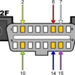
1.4. Standard Pinout of the OBD2 DLC
The OBD2 DLC has a standardized pinout, meaning that each pin is assigned a specific function. Here’s a general overview of the typical pinout:
| Pin | Function |
|---|---|
| 2 | SAE J1850 Bus Positive |
| 4 | Chassis Ground |
| 5 | Signal Ground |
| 6 | CAN High (J-2284) |
| 7 | ISO 9141-2 K Line |
| 10 | SAE J1850 Bus Negative |
| 14 | CAN Low (J-2284) |
| 15 | ISO 9141-2 L Line |
| 16 | Battery Power (12V) |
Understanding this pinout can be helpful when troubleshooting issues with the OBD2 DLC or when connecting aftermarket devices.
1.5. Why is the OBD2 DLC Important?
The OBD2 DLC is essential for modern vehicle diagnostics and maintenance. It allows technicians and car owners to quickly identify and address issues, ensuring the vehicle operates efficiently and safely. Without a functioning OBD2 DLC, diagnosing problems can become significantly more challenging, often requiring more time and specialized equipment. Regular use of the OBD2 DLC with appropriate diagnostic tools can help prevent minor issues from becoming major, costly repairs.
2. Common Problems with the OBD2 DLC
Several issues can affect the functionality of the OBD2 DLC. These problems can range from simple fixes like blown fuses to more complex electrical issues. Recognizing these common problems can help you diagnose and address them effectively.
2.1. Physical Damage to the Connector
Physical damage is one of the most common issues with the OBD2 DLC. The connector can be damaged by accidental impacts, mishandling of diagnostic tools, or wear and tear over time. Bent or broken pins can prevent proper communication between the diagnostic tool and the vehicle’s computer.
Symptoms:
- Visible damage to the connector
- Difficulty plugging in diagnostic tools
- Intermittent or no connection with diagnostic tools
Troubleshooting Steps:
- Visual Inspection: Carefully inspect the connector for any signs of damage, such as bent or broken pins, cracks, or loose connections.
- Pin Straightening: If any pins are bent, gently attempt to straighten them using a small, precise tool. Be careful not to break the pins.
- Connector Replacement: If the connector is severely damaged, it may need to be replaced. You can purchase replacement OBD2 DLC connectors from automotive parts suppliers.
2.2. Blown Fuses
The OBD2 DLC is typically powered by a fuse in the vehicle’s fuse box. A blown fuse can cut off power to the connector, preventing any communication with diagnostic tools.
Symptoms:
- No power to the OBD2 DLC
- Diagnostic tool fails to connect
- Check engine light may or may not be illuminated
Troubleshooting Steps:
- Locate the Fuse Box: Refer to your vehicle’s owner’s manual to find the location of the fuse box.
- Identify the OBD2 Fuse: Identify the fuse that powers the OBD2 DLC. The owner’s manual should provide a diagram indicating the fuse’s location.
- Check the Fuse: Remove the fuse and inspect it. If the filament inside the fuse is broken, the fuse is blown and needs to be replaced.
- Replace the Fuse: Replace the blown fuse with a new fuse of the same amperage rating.
- Test the Connection: After replacing the fuse, try connecting a diagnostic tool to the OBD2 DLC to see if it now has power and can communicate with the vehicle’s computer.
2.3. Wiring Issues
Wiring issues, such as broken, frayed, or corroded wires, can also cause problems with the OBD2 DLC. These issues can disrupt the electrical signals needed for communication between the diagnostic tool and the vehicle’s computer.
Symptoms:
- Intermittent connection with diagnostic tools
- No connection with diagnostic tools
- Error messages on the diagnostic tool
- Check engine light illuminated
Troubleshooting Steps:
- Visual Inspection: Inspect the wiring connected to the OBD2 DLC for any signs of damage, such as broken, frayed, or corroded wires.
- Continuity Testing: Use a multimeter to perform a continuity test on the wires. Disconnect the battery before testing to avoid electrical shock. Check for continuity between the OBD2 DLC connector and the corresponding pins on the vehicle’s computer.
- Repair or Replace Wires: If you find any damaged wires, repair them using electrical tape or wire connectors. If the damage is extensive, replace the entire wiring harness.
2.4. Grounding Problems
Proper grounding is essential for the OBD2 DLC to function correctly. A poor or missing ground connection can prevent the diagnostic tool from communicating with the vehicle’s computer.
Symptoms:
- No connection with diagnostic tools
- Intermittent connection with diagnostic tools
- Error messages on the diagnostic tool
Troubleshooting Steps:
- Locate the Ground Wire: Identify the ground wire for the OBD2 DLC. This is typically a black wire connected to the chassis ground.
- Check the Ground Connection: Ensure that the ground wire is securely connected to the chassis ground. Check for any signs of corrosion or loose connections.
- Clean the Ground Connection: If the ground connection is corroded, clean it using a wire brush or sandpaper.
- Test the Ground Connection: Use a multimeter to test the ground connection. There should be minimal resistance between the ground wire and the chassis ground.
2.5. CAN Bus Issues
The CAN (Controller Area Network) bus is a communication network that allows various electronic control units (ECUs) in the vehicle to communicate with each other. Problems with the CAN bus can affect the OBD2 DLC’s ability to communicate with the vehicle’s computer.
Symptoms:
- No connection with diagnostic tools
- Error messages related to CAN bus communication
- Multiple system failures
- Check engine light illuminated
Troubleshooting Steps:
- Check CAN Bus Wiring: Inspect the CAN bus wiring for any signs of damage, such as broken, frayed, or corroded wires.
- Test CAN Bus Voltage: Use a multimeter to test the voltage on the CAN bus wires. The voltage should be within the specified range (typically around 2.5V).
- Isolate the Problem: Disconnect ECUs one by one to see if the CAN bus communication is restored. This can help identify the faulty ECU that is causing the problem.
- Consult a Professional: CAN bus issues can be complex and may require specialized diagnostic tools and expertise. If you are unable to resolve the issue yourself, consult a professional mechanic.
2.6. Software or Firmware Issues
In some cases, the problem may not be with the OBD2 DLC itself, but with the diagnostic tool’s software or firmware. Outdated or corrupted software can prevent the tool from communicating with the vehicle’s computer.
Symptoms:
- Diagnostic tool fails to connect
- Error messages on the diagnostic tool
- Inaccurate data readings
Troubleshooting Steps:
- Update Software: Ensure that your diagnostic tool has the latest software updates installed. Check the manufacturer’s website for updates and follow the instructions to install them.
- Reinstall Software: If updating the software does not resolve the issue, try reinstalling it. This can help fix any corrupted files or settings.
- Test with Another Tool: If possible, try connecting a different diagnostic tool to the OBD2 DLC to see if it can communicate with the vehicle’s computer. This can help determine whether the problem is with the tool or the vehicle.
By understanding these common problems and following the troubleshooting steps, you can effectively diagnose and address issues with the OBD2 DLC in your Mercedes-Benz.
3. Step-by-Step Troubleshooting Guide for the OBD2 DLC
Troubleshooting the OBD2 DLC involves a systematic approach to identify and resolve any issues that prevent proper communication between your diagnostic tool and the vehicle’s computer. Here’s a detailed guide to help you through the process.
3.1. Tools and Equipment Needed
Before you begin troubleshooting, gather the necessary tools and equipment:
- Diagnostic Tool: A compatible OBD2 scanner or diagnostic tool.
- Multimeter: For testing voltage, continuity, and ground connections.
- Fuse Puller: To safely remove and inspect fuses.
- Wiring Diagram: A wiring diagram for your specific Mercedes-Benz model, showing the OBD2 DLC connections.
- Basic Hand Tools: Screwdrivers, pliers, and wire strippers.
- Contact Cleaner: To clean corroded connections.
- Replacement Fuses: Fuses of the correct amperage rating.
- Safety Glasses and Gloves: For personal protection.
3.2. Initial Inspection
- Visual Check:
- Inspect the OBD2 DLC for any physical damage, such as bent or broken pins, cracks, or loose connections.
- Ensure the connector is clean and free from debris.
- Check the Fuses:
- Consult your vehicle’s owner’s manual to locate the fuse that powers the OBD2 DLC.
- Use a fuse puller to remove the fuse and inspect it. If the filament inside is broken, replace it with a new fuse of the same amperage rating.
3.3. Testing for Power and Ground
- Battery Voltage Test:
- Turn the ignition to the “ON” position (without starting the engine).
- Use a multimeter to test for voltage at pin 16 of the OBD2 DLC. You should see battery voltage (approximately 12V).
- If there is no voltage, trace the wiring back to the fuse box and check for any breaks or loose connections.
- Ground Connection Test:
- Set the multimeter to the continuity setting.
- Test for continuity between pin 4 (chassis ground) and a known good ground point on the vehicle’s chassis.
- Test for continuity between pin 5 (signal ground) and a known good ground point.
- If there is no continuity, inspect the ground wires and connections for corrosion or damage. Clean or repair as necessary.
3.4. Checking the CAN Bus
- CAN Bus Voltage Test:
- With the ignition in the “ON” position, use a multimeter to measure the voltage between pin 6 (CAN High) and pin 4 (chassis ground). You should see approximately 2.5V.
- Measure the voltage between pin 14 (CAN Low) and pin 4 (chassis ground). You should also see approximately 2.5V.
- Measure the voltage between pin 6 (CAN High) and pin 14 (CAN Low). The voltage should be close to 0V.
- CAN Bus Resistance Test:
- Turn the ignition OFF and disconnect the battery.
- Measure the resistance between pin 6 (CAN High) and pin 14 (CAN Low). The resistance should be approximately 60 ohms.
- If the voltage or resistance readings are incorrect, there may be a problem with the CAN bus wiring or one of the ECUs connected to the bus.
3.5. Testing the K-Line and L-Line (ISO 9141-2)
- Voltage Test:
- With the ignition in the “ON” position, use a multimeter to measure the voltage at pin 7 (K-Line). The voltage should be between 5V and 12V.
- If there is no voltage, check the wiring and connections for any breaks or shorts.
- Pin 15 (L-Line) is typically not used in most modern vehicles, but you can still check for any voltage.
3.6. Verifying Communication with a Diagnostic Tool
- Connect the Diagnostic Tool:
- Plug your diagnostic tool into the OBD2 DLC.
- Turn the ignition to the “ON” position.
- Attempt Communication:
- Follow the instructions on your diagnostic tool to attempt to connect to the vehicle’s computer.
- If the tool fails to connect, check the tool’s software and firmware to ensure they are up to date.
- Troubleshoot Communication Errors:
- If you receive any error messages, consult the diagnostic tool’s manual for troubleshooting steps.
- Try connecting the tool to another vehicle to see if the problem is with the tool or the vehicle.
3.7. Advanced Troubleshooting Steps
- Wiring Issues:
- If you suspect a wiring issue, use a wiring diagram to trace the OBD2 DLC wires back to the vehicle’s computer.
- Check for any breaks, shorts, or loose connections in the wiring.
- Use a multimeter to perform continuity tests on the wires.
- Grounding Problems:
- Ensure that the OBD2 DLC is properly grounded to the vehicle’s chassis.
- Check the ground connections for corrosion or damage.
- Clean or repair the ground connections as necessary.
- ECU Issues:
- If you suspect an issue with one of the ECUs connected to the CAN bus, disconnect the ECU and see if communication with the OBD2 DLC is restored.
- Consult a professional mechanic for further diagnosis and repair.
3.8. Seeking Professional Help
If you have followed these troubleshooting steps and are still unable to resolve the issue with the OBD2 DLC, it may be necessary to seek professional help. A qualified mechanic with specialized diagnostic tools and expertise can further diagnose and repair the problem. Contact MERCEDES-DIAGNOSTIC-TOOL.EDU.VN at +1 (641) 206-8880 for expert advice and solutions.
By following this step-by-step guide, you can effectively troubleshoot the OBD2 DLC in your Mercedes-Benz and ensure that it is functioning correctly.
4. Advanced Diagnostic Techniques for OBD2 DLC Issues
When basic troubleshooting steps don’t resolve OBD2 DLC issues, employing advanced diagnostic techniques can help pinpoint the root cause of the problem. These techniques often involve specialized tools and a deeper understanding of vehicle electronics.
4.1. Using an Oscilloscope
An oscilloscope is a valuable tool for analyzing electrical signals in the OBD2 DLC. It displays voltage variations over time, allowing you to identify signal abnormalities that a multimeter might miss.
How to Use an Oscilloscope:
- Connect the Oscilloscope: Connect the oscilloscope probes to the relevant pins on the OBD2 DLC (e.g., CAN High, CAN Low).
- Set the Time and Voltage Scales: Adjust the time and voltage scales to capture the signal waveforms effectively.
- Analyze the Waveforms: Look for any distortions, noise, or missing signals in the waveforms. Compare the waveforms to known good signals to identify any discrepancies.
Example:
- CAN Bus Analysis: An oscilloscope can reveal issues like signal reflections, voltage drops, or incorrect termination resistance in the CAN bus. According to a study by the Society of Automotive Engineers (SAE), proper CAN bus signal integrity is crucial for reliable communication between ECUs.
4.2. CAN Bus Diagnostics
The CAN (Controller Area Network) bus is a critical communication network in modern vehicles. Diagnosing CAN bus issues requires a systematic approach.
Steps for CAN Bus Diagnostics:
- Check Termination Resistors: The CAN bus should have a 120-ohm resistor at each end of the network. Use a multimeter to measure the resistance between CAN High and CAN Low with the ignition off. The reading should be approximately 60 ohms.
- Isolate ECUs: Disconnect ECUs one by one to see if communication is restored. This helps identify a faulty ECU that is disrupting the CAN bus.
- Use a CAN Bus Analyzer: A CAN bus analyzer can monitor CAN bus traffic, display error messages, and help identify the source of communication problems.
Example:
- Faulty ECU: A faulty ECU can flood the CAN bus with erroneous messages, preventing other ECUs from communicating. Disconnecting the faulty ECU can restore normal communication.
4.3. Using a Breakout Box
A breakout box is a diagnostic tool that connects to the OBD2 DLC and provides access to each pin. It allows you to easily measure voltages, resistances, and signal waveforms without having to probe the connector directly.
How to Use a Breakout Box:
- Connect the Breakout Box: Plug the breakout box into the OBD2 DLC.
- Connect Test Leads: Connect test leads from the breakout box to a multimeter or oscilloscope.
- Measure Signals: Measure voltages, resistances, and signal waveforms at each pin to diagnose any issues.
Example:
- Voltage Drop: A breakout box can help identify voltage drops on specific pins, indicating a wiring issue or a faulty connection.
4.4. Performing a Network Scan
A network scan involves using a diagnostic tool to scan all the ECUs in the vehicle and identify any communication errors or fault codes.
How to Perform a Network Scan:
- Connect the Diagnostic Tool: Plug a compatible diagnostic tool into the OBD2 DLC.
- Initiate a Network Scan: Follow the tool’s instructions to initiate a network scan.
- Analyze the Results: Review the scan results to identify any ECUs that are not communicating or have fault codes related to communication issues.
Example:
- Lost Communication Codes: A network scan might reveal “lost communication” codes for specific ECUs, indicating a problem with the CAN bus or the ECU itself.
4.5. Checking for Short Circuits and Open Circuits
Short circuits and open circuits can cause a variety of OBD2 DLC issues. Use a multimeter to check for these conditions.
How to Check for Short Circuits:
- Disconnect the Battery: Disconnect the negative battery terminal to prevent electrical damage.
- Set the Multimeter: Set the multimeter to the continuity setting.
- Check for Continuity: Check for continuity between each pin on the OBD2 DLC and ground. There should be no continuity.
How to Check for Open Circuits:
- Disconnect the Battery: Disconnect the negative battery terminal.
- Set the Multimeter: Set the multimeter to the continuity setting.
- Check for Continuity: Check for continuity between each pin on the OBD2 DLC and its corresponding pin on the ECU. There should be continuity.
Example:
- Short to Ground: A short circuit to ground on the CAN High or CAN Low wire can disrupt CAN bus communication.
- Open Circuit: An open circuit in the power or ground wire to the OBD2 DLC can prevent the connector from functioning.
4.6. Using Freeze Frame Data
Freeze frame data captures the operating conditions of the vehicle at the moment a fault code is stored. This information can help diagnose intermittent OBD2 DLC issues.
How to Use Freeze Frame Data:
- Retrieve Freeze Frame Data: Use a diagnostic tool to retrieve the freeze frame data associated with any communication-related fault codes.
- Analyze the Data: Analyze the data to identify any unusual operating conditions that may have contributed to the problem.
Example:
- Low Voltage: Freeze frame data might show a low voltage condition at the time a communication code was stored, indicating a problem with the vehicle’s electrical system.
By employing these advanced diagnostic techniques, you can effectively troubleshoot complex OBD2 DLC issues and ensure that your Mercedes-Benz is operating correctly. For expert assistance, contact MERCEDES-DIAGNOSTIC-TOOL.EDU.VN at +1 (641) 206-8880.
5. Preventing OBD2 DLC Problems
Preventing issues with your Mercedes-Benz’s OBD2 DLC involves regular maintenance and careful handling. Taking proactive steps can save you time and money by avoiding common problems.
5.1. Regular Maintenance Checks
Regular maintenance checks are essential for preventing OBD2 DLC problems. These checks should include inspecting the connector for physical damage, ensuring proper wiring connections, and verifying that the related fuses are in good condition.
Checklist for Regular Maintenance:
- Inspect the Connector:
- Visually inspect the OBD2 DLC for any signs of physical damage, such as bent or broken pins, cracks, or loose connections.
- Ensure the connector is clean and free from debris.
- Check Wiring Connections:
- Inspect the wiring connected to the OBD2 DLC for any signs of damage, such as broken, frayed, or corroded wires.
- Ensure that all connections are secure and properly insulated.
- Verify Fuse Condition:
- Check the fuse that powers the OBD2 DLC to ensure that it is not blown or damaged.
- Replace any damaged fuses with new fuses of the correct amperage rating.
- Test Voltage and Ground:
- Use a multimeter to test for proper voltage and ground connections at the OBD2 DLC.
- Ensure that the voltage is within the specified range and that the ground connection is secure.
5.2. Proper Handling of Diagnostic Tools
Proper handling of diagnostic tools is crucial to prevent damage to the OBD2 DLC. Avoid forcing the diagnostic tool into the connector, and always ensure that the tool is properly aligned before inserting it.
Tips for Proper Handling:
- Align the Tool: Always align the diagnostic tool properly with the OBD2 DLC before inserting it.
- Avoid Force: Do not force the diagnostic tool into the connector. If you encounter resistance, check for any obstructions or misalignments.
- Use Quality Tools: Use high-quality diagnostic tools that are designed to fit the OBD2 DLC properly.
- Store Tools Properly: Store diagnostic tools in a safe and secure location to prevent damage.
5.3. Protecting the Connector from Environmental Factors
Environmental factors, such as moisture, dirt, and extreme temperatures, can damage the OBD2 DLC. Protect the connector by using a protective cap or cover when it is not in use.
Protective Measures:
- Use a Protective Cap: Use a protective cap or cover to shield the OBD2 DLC from moisture, dirt, and debris.
- Keep the Interior Clean: Regularly clean the interior of your vehicle to prevent dirt and dust from accumulating around the OBD2 DLC.
- Avoid Extreme Temperatures: Avoid exposing the OBD2 DLC to extreme temperatures, such as direct sunlight or freezing conditions.
- Apply Contact Cleaner: Periodically apply contact cleaner to the pins of the OBD2 DLC to prevent corrosion and ensure good electrical contact.
5.4. Regular Software Updates for Diagnostic Tools
Regular software updates for diagnostic tools are essential to ensure that they are compatible with the latest vehicle models and diagnostic protocols. Outdated software can cause communication problems and inaccurate readings.
Benefits of Regular Updates:
- Compatibility: Ensure that the diagnostic tool is compatible with the latest vehicle models and diagnostic protocols.
- Accuracy: Improve the accuracy of diagnostic readings and fault code interpretations.
- New Features: Gain access to new features and diagnostic capabilities.
- Bug Fixes: Resolve any software bugs or issues that may be affecting performance.
5.5. Avoiding Aftermarket Accessories That Interfere with the OBD2 System
Some aftermarket accessories can interfere with the OBD2 system and cause communication problems. Avoid using accessories that are not designed to be compatible with your vehicle’s OBD2 system.
Precautions:
- Research Compatibility: Before installing any aftermarket accessories, research their compatibility with your vehicle’s OBD2 system.
- Choose Reputable Brands: Choose accessories from reputable brands that have a proven track record of compatibility and reliability.
- Avoid Cheap Accessories: Avoid using cheap or poorly designed accessories that may cause electrical interference or damage to the OBD2 system.
- Consult a Professional: If you are unsure about the compatibility of an accessory, consult a professional mechanic.
By following these preventive measures, you can minimize the risk of OBD2 DLC problems and ensure that your Mercedes-Benz’s diagnostic system remains in good working order. For more expert advice, contact MERCEDES-DIAGNOSTIC-TOOL.EDU.VN at +1 (641) 206-8880.
6. The Future of OBD2 Technology
OBD2 technology has evolved significantly since its inception, and it continues to advance to meet the demands of modern vehicles. Understanding the future trends of OBD2 technology can help you stay informed and prepared for the changes ahead.
6.1. Enhanced Diagnostic Capabilities
Future OBD2 systems will offer enhanced diagnostic capabilities, providing more detailed and accurate information about vehicle performance. This will enable technicians and car owners to diagnose problems more quickly and effectively.
Improvements in Diagnostic Capabilities:
- Advanced Sensors: Integration of more advanced sensors to monitor a wider range of vehicle parameters.
- Improved Data Analysis: Use of sophisticated data analysis techniques to identify subtle issues and predict potential failures.
- Remote Diagnostics: Remote diagnostic capabilities that allow technicians to diagnose problems from a distance.
- Artificial Intelligence (AI): Integration of AI to assist in diagnosing complex issues and provide personalized recommendations.
6.2. Integration with Telematics Systems
OBD2 technology is increasingly being integrated with telematics systems, which provide real-time data about vehicle location, performance, and driver behavior. This integration can offer a range of benefits, including improved vehicle maintenance, enhanced safety, and reduced operating costs.
Benefits of Telematics Integration:
- Real-Time Monitoring: Real-time monitoring of vehicle performance and location.
- Predictive Maintenance: Predictive maintenance capabilities that can identify potential issues before they become major problems.
- Improved Safety: Enhanced safety features, such as automatic crash detection and emergency assistance.
- Fleet Management: Improved fleet management capabilities for businesses that operate a fleet of vehicles.
6.3. Cybersecurity Considerations
As OBD2 technology becomes more connected, cybersecurity becomes an increasingly important consideration. Protecting the OBD2 system from cyberattacks is essential to prevent unauthorized access to vehicle systems and data.
Cybersecurity Measures:
- Encryption: Use of encryption to protect data transmitted over the OBD2 system.
- Authentication: Implementation of strong authentication measures to prevent unauthorized access.
- Intrusion Detection: Intrusion detection systems that can identify and respond to cyberattacks.
- Regular Security Updates: Regular security updates to address any vulnerabilities in the OBD2 system.
6.4. Wireless OBD2 Adapters
Wireless OBD2 adapters are becoming increasingly popular, allowing users to connect to their vehicle’s OBD2 system using a smartphone or tablet. These adapters offer a convenient way to monitor vehicle performance, read fault codes, and perform basic diagnostic tests.
Benefits of Wireless Adapters:
- Convenience: Convenient wireless connectivity.
- Portability: Portable and easy to use.
- Cost-Effective: Cost-effective compared to traditional diagnostic tools.
- Real-Time Data: Real-time data monitoring on a smartphone or tablet.
6.5. Standardized Diagnostic Protocols
Efforts are underway to standardize diagnostic protocols across different vehicle manufacturers. This would make it easier for technicians and car owners to diagnose and repair vehicles, regardless of the make or model.
Benefits of Standardization:
- Improved Compatibility: Improved compatibility between diagnostic tools and vehicles.
- Reduced Complexity: Reduced complexity in diagnosing and repairing vehicles.
- Lower Costs: Lower costs for diagnostic tools and services.
- Enhanced Efficiency: Enhanced efficiency in vehicle maintenance and repair.
The future of OBD2 technology promises enhanced diagnostic capabilities, seamless integration with telematics systems, and improved cybersecurity measures. Staying informed about these advancements can help you make the most of your vehicle’s diagnostic system and ensure that it remains in good working order. For expert assistance, contact MERCEDES-DIAGNOSTIC-TOOL.EDU.VN at +1 (641) 206-8880.
7. Case Studies: Resolving OBD2 DLC Issues
Examining real-world case studies can provide valuable insights into how to effectively resolve OBD2 DLC issues. These examples illustrate common problems, troubleshooting techniques, and successful solutions.
7.1. Case Study 1: Physical Damage to the Connector
Problem:
A Mercedes-Benz C-Class owner reported that their diagnostic tool would not connect to the OBD2 DLC. Upon inspection, the technician found that several pins in the connector were bent and damaged.
Troubleshooting Steps:
- Visual Inspection: The technician visually inspected the OBD2 DLC and confirmed that several pins were bent.
- Pin Straightening: The technician attempted to straighten the bent pins using a small, precise tool. However, one of the pins broke off during the process.
- Connector Replacement: The technician decided to replace the entire OBD2 DLC connector. They purchased a replacement connector from an automotive parts supplier.
- Wiring Connections: The technician carefully disconnected the wires from the old connector and connected them to the new connector, ensuring that each wire was properly seated and secured.
- Testing: After replacing the connector, the technician connected the diagnostic tool to the OBD2 DLC and confirmed that it could now communicate with the vehicle’s computer.
Solution:
The OBD2 DLC connector was successfully replaced, resolving the communication issue.
Lessons Learned:
- Physical damage is a common cause of OBD2 DLC problems.
- Attempting to straighten bent pins can be risky, as the pins may break.
- Replacing the entire connector is often the best solution for severe physical damage.
7.2. Case Study 2: Blown Fuse
Problem:
A Mercedes-Benz E-Class owner reported that their diagnostic tool would not power on when connected to the OBD2 DLC.
Troubleshooting Steps:
- Fuse Location: The technician consulted the vehicle’s owner’s manual to locate the fuse that powers the OBD2 DLC.
- Fuse Inspection: The technician removed the fuse and inspected it. They found that the filament inside the fuse was broken, indicating that the fuse was blown.
- Fuse Replacement: The technician replaced the blown fuse with a new fuse of the same amperage rating.
- Testing: After replacing the fuse, the technician connected the diagnostic tool to the OBD2 DLC and confirmed that it now powered on and could communicate with the vehicle’s computer.
Solution:
The blown fuse was replaced, resolving the power issue.
Lessons Learned:
- A blown fuse is a common cause of OBD2 DLC problems.
- Always check the fuses before attempting more complex troubleshooting steps.
- Replace blown fuses with new fuses of the correct amperage rating.
7.3. Case Study 3: Wiring Issues
Problem:
A Mercedes-Benz S-Class owner reported intermittent communication problems with their diagnostic tool. Sometimes the tool would connect, and sometimes it would not.
Troubleshooting Steps:
- Visual Inspection: The technician visually inspected the wiring connected to the OBD2 DLC and found that one of the wires was frayed and partially broken.
- Wire Repair: The technician repaired the damaged wire using electrical tape and a wire connector.
- Testing: After repairing the wire, the technician connected the diagnostic tool to the OBD2 DLC and confirmed that the communication problems were resolved.
Solution:
The damaged wire was repaired, resolving the intermittent communication issue.
Lessons Learned:
- Wiring issues can cause intermittent OBD2 DLC problems.
- Carefully inspect the wiring for any signs of damage.
- Repair damaged wires using appropriate techniques and materials.
7.4. Case Study 4: Grounding Problems
Problem:
A Mercedes-Benz GLC owner reported that their diagnostic tool would not connect to the OBD2 DLC.
Troubleshooting Steps:
- Ground Connection: The technician located the ground wire for the OBD2 DLC and found that it was loose and corroded.
- Ground Cleaning: The technician cleaned the ground connection using a wire brush and sandpaper.
- Ground Securing: The technician secured the ground wire to the chassis using a new bolt and washer.
- Testing: After cleaning and securing the ground connection, the technician connected the diagnostic tool to the OBD2 DLC and confirmed that it could now communicate with the vehicle’s computer.
Solution:
The loose and corroded ground connection was cleaned and secured, resolving the communication issue.
Lessons Learned:
- Grounding problems can prevent the OBD2 DLC from functioning correctly.
- Ensure that the ground connection is clean, secure, and properly connected to the chassis.
These case studies illustrate the importance of systematic troubleshooting and careful attention to detail when resolving OBD2 DLC issues. By following these examples and learning from the experiences of others, you can effectively diagnose and repair problems with your Mercedes-Benz’s diagnostic system. Contact MERCEDES-DIAGNOSTIC-TOOL.EDU.VN at +1 (641) 206-8880 for additional support.
8. Choosing the Right OBD2 Diagnostic Tool for Your Mercedes-Benz
Selecting the appropriate OBD2 diagnostic tool for your Mercedes-Benz is crucial for accurate and effective vehicle maintenance. Different tools offer varying levels of functionality and compatibility, so it’s essential to choose one that meets your specific needs.
8.1. Types of OBD2 Diagnostic Tools
There are several types of OBD2 diagnostic tools available, each with its own set of features and capabilities.
Basic OBD2 Scanners:
- Functionality: These scanners are designed to read and clear basic diagnostic trouble codes (DTCs).
- Use Cases: Suitable for diagnosing common issues, such as check engine light problems.
- Pros: Affordable and easy to use.
- Cons: Limited functionality