OBD2, the On-Board Diagnostics II, became mandatory in different regions at different times. This article provides a comprehensive look at the history, standards, and future of OBD2, brought to you by MERCEDES-DIAGNOSTIC-TOOL.EDU.VN, your trusted resource for Mercedes-Benz diagnostics and repair. Understanding when OBD2 became mandatory is crucial for anyone working with or owning a vehicle, and we aim to provide clarity and solutions in this guide, focusing on emission control and diagnostic tools.
Contents
- 1. Understanding OBD2: The Basics
- 2. Is Your Car OBD2 Compliant?
- 3. The Genesis of OBD2: A History
- 4. What Does the Future Hold for OBD2?
- 5. Exploring OBD2 Standards: SAE J1962
- 6. OBD2 Connector Types: A vs. B
- 7. The Role of CAN Bus in OBD2: ISO 15765-4
- 8. Understanding OBD2 CAN Identifiers
- 9. Decoding OBD2 Messages: A Closer Look
- 10. Unpacking OBD2 Modes (Services)
- 11. The Significance of OBD2 Parameter IDs (PIDs)
- 12. Logging and Decoding OBD2 Data: A Practical Guide
- 13. Multi-Frame OBD2 Communication: ISO-TP
- 14. Extracting the Vehicle Identification Number (VIN) via OBD2
- 15. Understanding OBD2 Diagnostic Trouble Codes (DTCs)
- 16. Real-World OBD2 Data Logging Use Cases
- 17. Enhance Your Mercedes-Benz with Expert Diagnostics
- 18. Ready to Take Control of Your Mercedes-Benz?
- FAQ: Decoding OBD2 Mysteries
- Connect with Us
1. Understanding OBD2: The Basics
OBD2 is a vehicle’s self-diagnostic system, providing access to diagnostic trouble codes (DTCs) and real-time data via a standardized protocol. It enhances troubleshooting by allowing mechanics to quickly identify and address issues.
Have you ever wondered about the malfunction indicator light on your dashboard? That’s OBD2 at work. When the light appears, it signifies a problem detected by the vehicle’s self-diagnostic system. Mechanics use OBD2 scanners to connect to the car’s OBD2 16-pin connector, usually found near the steering wheel. The scanner sends requests, and the car responds with data like speed, fuel level, and DTCs. This streamlined process significantly speeds up diagnostics and repairs.
The malfunction indicator light alerts drivers to potential issues detected by the OBD2 system.
2. Is Your Car OBD2 Compliant?
Most modern vehicles support OBD2, operating primarily on the CAN bus. However, compliance depends on the vehicle’s manufacturing date and region of sale.
Determining OBD2 compliance can be straightforward. While almost all new cars, excluding electric vehicles, support OBD2, older vehicles may present a challenge. Even if an older car has a 16-pin OBD2 connector, it might not fully support the protocol. A quick check involves verifying where and when the car was originally sold. For instance, in the United States, OBD2 became mandatory for cars and light trucks in 1996.
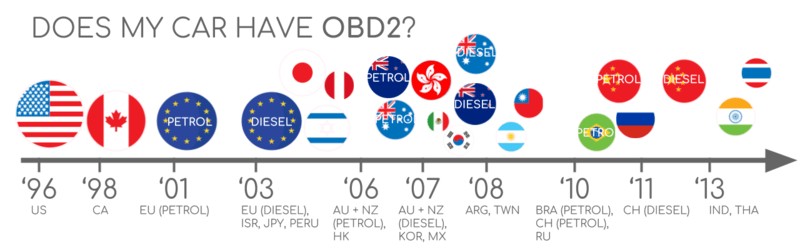
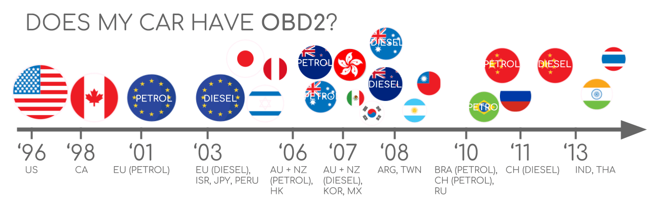 OBD2 Compliance Chart
A visual chart indicating OBD2 compliance timelines for different regions.
3. The Genesis of OBD2: A History
OBD2 originated in California, driven by the California Air Resources Board (CARB) to monitor emissions in new cars starting in 1991. This initiative led to the standardization of DTCs and connectors by the Society of Automotive Engineers (SAE).
The history of OBD2 is deeply rooted in environmental concerns and regulatory efforts. The California Air Resources Board (CARB) played a pivotal role, mandating OBD in all new cars from 1991 onward to control emissions. Following this, the Society of Automotive Engineers (SAE) standardized DTCs and the OBD connector, ensuring uniformity across manufacturers. This standardization is documented under SAE J1962. The implementation of OBD2 then proceeded in phases across different regions:
- 1996: USA mandated OBD2 for cars and light trucks
- 2001: EU required OBD2 for gasoline cars
- 2003: EU extended the requirement to diesel cars (EOBD)
- 2005: USA included medium duty vehicles in the OBD2 mandate
- 2008: USA required cars to use ISO 15765-4 (CAN) as the foundation for OBD2
- 2010: USA extended OBD2 requirements to heavy-duty vehicles
A timeline illustrating the evolution of OBD2 standards for emission control.
4. What Does the Future Hold for OBD2?
The future of OBD2 involves adaptations for electric vehicles, enhanced communication protocols like WWH-OBD, and the potential integration of telematics through OBD3. These advancements aim to improve emission control and diagnostic capabilities.
While OBD2 has been a cornerstone in vehicle diagnostics, its future is set to evolve significantly. Originally designed for emission control and testing, legislated OBD2 faces new challenges with the rise of electric vehicles (EVs). Most modern EVs do not support standard OBD2 requests, opting instead for OEM-specific UDS communication. This shift makes it difficult to decode data from EVs, except in cases where decoding rules have been reverse-engineered.
An illustration of future trends in OBD, including remote diagnostics.
5. Exploring OBD2 Standards: SAE J1962
SAE J1962 specifies the OBD2 connector, ensuring easy access to vehicle data. This standard defines the physical interface used to retrieve diagnostic information from the vehicle.
The OBD2 connector, detailed in SAE J1962 and ISO 15031-3, is a 16-pin interface that allows users to access data from their vehicles. Some key aspects of this connector include:
- Location: Typically found near the steering wheel, though it may be hidden
- Power Supply: Pin 16 provides battery power, even when the ignition is off
- Pinout Variation: The OBD2 pinout varies based on the communication protocol used
- CAN Bus Integration: The most common protocol, CAN bus, uses pins 6 (CAN-H) and 14 (CAN-L)
The OBD2 connector pinout, ensuring standardized access to vehicle data.
6. OBD2 Connector Types: A vs. B
Two types of OBD2 connectors exist: Type A, commonly found in cars, and Type B, used in medium and heavy-duty vehicles. These types differ in power supply output and baud rate.
In practice, distinguishing between Type A and Type B OBD2 connectors is important. Type A is predominantly used in cars, delivering a 12V power supply, while Type B is standard in medium and heavy-duty vehicles, providing a 24V power supply. The baud rate also differs, with cars typically using 500K and heavy-duty vehicles often using 250K, though recent models may support 500K.
A comparison of OBD2 Connector Type A and Type B.
7. The Role of CAN Bus in OBD2: ISO 15765-4
ISO 15765-4 standardizes the CAN interface for test equipment, specifying bit-rates, CAN IDs, and data length. It ensures reliable communication between diagnostic tools and the vehicle.
Since 2008, CAN bus has been the mandatory lower-layer protocol for OBD2 in all cars sold in the US, as defined by ISO 15765. ISO 15765-4, also known as Diagnostics over CAN or DoCAN, outlines specific restrictions applied to the CAN standard. Key specifications include:
- Bit-rate: Must be either 250K or 500K
- CAN IDs: Can be 11-bit or 29-bit
- Specific CAN IDs: Used for OBD requests and responses
- Data Length: Diagnostic CAN frame data length must be 8 bytes
- Cable Length: The OBD2 adapter cable must be max 5 meters
The relationship between OBD2 and CAN bus, highlighting ISO 15765.
8. Understanding OBD2 CAN Identifiers
OBD2 communication relies on request/response messages using 11-bit or 29-bit CAN IDs. These identifiers facilitate communication between the diagnostic tool and the vehicle’s ECUs.
All OBD2 communication involves request and response messages. In most cars, 11-bit CAN IDs are used, with the ‘Functional Addressing’ ID being 0x7DF. This ID queries all OBD2 compatible ECUs to check if they have data to report on the requested parameter. Conversely, CAN IDs 0x7E0-0x7E7 can be used for ‘Physical Addressing’ requests from specific ECUs. ECUs respond with 11-bit IDs ranging from 0x7E8 to 0x7EF, with 0x7E8 (ECM, Engine Control Module) being the most common.
The structure of OBD2 request and response frames.
9. Decoding OBD2 Messages: A Closer Look
OBD2 messages consist of an identifier, data length, mode, parameter ID (PID), and data bytes. Understanding these components is key to interpreting OBD2 data.
An OBD2 message comprises an identifier, data length, mode, parameter ID (PID), and data bytes. To illustrate, consider a request/response for ‘Vehicle Speed.’ The external tool sends a request message to the car with CAN ID 0x7DF, including Mode 0x01 and PID 0x0D. The car responds via CAN ID 0x7E8 with the vehicle speed value in the 4th byte, for example, 0x32 (50 in decimal form), indicating a speed of 50 km/h.
The anatomy of an OBD2 message, detailing its components.
10. Unpacking OBD2 Modes (Services)
OBD2 includes 10 diagnostic services, or modes, for accessing real-time data, DTCs, and freeze frame data. Not all vehicles support all modes, but these services provide valuable diagnostic information.
There are 10 OBD2 diagnostic services (or modes). Mode 0x01 provides current real-time data, while others display or clear diagnostic trouble codes (DTCs) or show freeze frame data. Vehicles do not have to support all OBD2 modes and may support modes outside the 10 standardized modes (OEM-specific). In OBD2 messages, the mode is in the 2nd byte. In the request, the mode is included directly (e.g. 0x01), while in the response, 0x40 is added to the mode (resulting in 0x41).
The 10 standardized OBD2 diagnostic services, or modes.
11. The Significance of OBD2 Parameter IDs (PIDs)
Each OBD2 mode contains parameter IDs (PIDs) that specify the data being requested. Mode 0x01, for example, includes ~200 standardized PIDs for real-time data like speed, RPM, and fuel level.
Each OBD2 mode contains parameter IDs (PIDs). For example, mode 0x01 contains approximately 200 standardized PIDs with real-time data on speed, RPM, and fuel level. However, vehicles don’t have to support all OBD2 PIDs in a mode, with most supporting only a small subset. One special PID is mode 0x01 PID 0x00. If an emissions-related ECU supports any OBD2 services, it must support mode 0x01 PID 0x00. This PID informs whether the vehicle ECU supports PIDs 0x01-0x20, making it a fundamental OBD2 compatibility test. Further, PIDs 0x20, 0x40, …, 0xC0 can determine support for the remaining mode 0x01 PIDs.
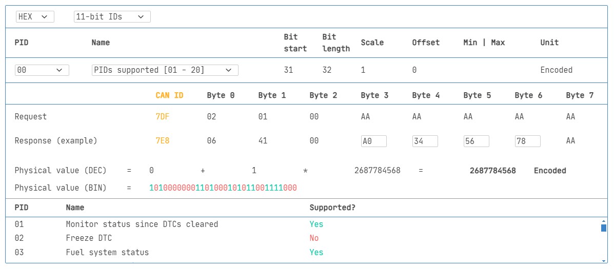 OBD2 PIDs Overview
12. Logging and Decoding OBD2 Data: A Practical Guide
Logging and decoding OBD2 data involves configuring a CAN bus data logger, transmitting custom CAN frames, and using software tools to decode the data into physical values.
To log OBD2 data, tools like the CANedge are valuable. The CANedge allows configuration of custom CAN frames for OBD2 logging and connects to the vehicle via an OBD2-DB9 adapter cable. To start, you should test the bit-rate, IDs, and supported PIDs to ensure compatibility. Then, configure your transmit list with PIDs of interest, considering CAN IDs, spacing, battery drain, and filters. Once configured, the device can log raw OBD2 data. Finally, analyze and visualize your data by decoding the raw OBD2 data into physical values using tools that support DBC decoding.
The process of logging OBD2 data using a CAN bus data logger.
13. Multi-Frame OBD2 Communication: ISO-TP
ISO-TP (ISO 15765-2) is used to transport OBD2 data exceeding 8 bytes, enabling communication of the Vehicle Identification Number (VIN) and Diagnostic Trouble Codes (DTCs) through segmentation, flow control, and reassembly.
All OBD2 data is communicated on the CAN bus through the ISO-TP (transport protocol) as per ISO 15765-2. This enables communication of payloads exceeding 8 bytes, necessary when extracting the Vehicle Identification Number (VIN) or Diagnostic Trouble Codes (DTCs). Here, ISO 15765-2 enables segmentation, flow control, and reassembly. Multi-frame OBD2 communication requires flow control frames.
ISO-TP frame types used in OBD2 communication.
14. Extracting the Vehicle Identification Number (VIN) via OBD2
The Vehicle Identification Number (VIN) can be extracted using mode 0x09 and PID 0x02, enabling applications in telematics and diagnostics. The process involves a tester tool sending a Single Frame request with the PCI field (0x02), request service identifier (0x09) and PID (0x02). The vehicle responds with a First Frame containing the PCI, length (0x014 = 20 bytes), mode (0x49, i.e. 0x09 + 0x40) and PID (0x02). Following the PID is the byte 0x01, which is the Number Of Data Items (NODI), and the remaining 17 bytes equal the VIN, which can be translated from HEX to ASC.
To extract the Vehicle Identification Number from a vehicle using OBD2 requests, you use mode 0x09 and PID 0x02:
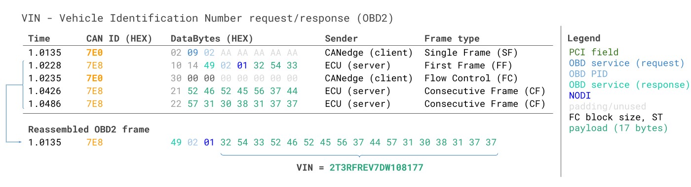 VIN Extraction Example
15. Understanding OBD2 Diagnostic Trouble Codes (DTCs)
OBD2 mode 0x03 is used to request emissions-related Diagnostic Trouble Codes (DTCs). These codes, typically 2 bytes each, help identify specific issues within the vehicle.
OBD2 can request emissions-related Diagnostic Trouble Codes (DTCs) using mode 0x03, i.e., ‘Show stored Diagnostic Trouble Codes.’ The targeted ECU(s) will respond with the number of DTCs they have stored, with each DTC taking up 2 data bytes. The 2-byte DTC value is split into a ‘category’ defined by the first 2 bits and a 4-digit code (displayed in hexadecimal) defined by the remaining 14 bits. Decoded DTC values can be looked up in OBD2 DTC lookup tools.
Decoding Diagnostic Trouble Codes (DTCs) in OBD2.
16. Real-World OBD2 Data Logging Use Cases
OBD2 data logging is used in various applications, including reducing fuel costs, improving driving habits, predictive maintenance, and serving as a vehicle blackbox for insurance purposes.
OBD2 data from cars and light trucks has diverse applications:
- Logging data from cars: Reduce fuel costs, improve driving, test prototype parts, and manage insurance
- Real-time car diagnostics: Stream OBD2 data in real-time to diagnose vehicle issues
- Predictive maintenance: Monitor vehicles via IoT OBD2 loggers to predict and avoid breakdowns
- Vehicle blackbox logger: Serve as a ‘blackbox’ for vehicles, providing data for disputes or diagnostics
Various applications of OBD2 data logging in vehicles.
17. Enhance Your Mercedes-Benz with Expert Diagnostics
At MERCEDES-DIAGNOSTIC-TOOL.EDU.VN, we understand the nuances of Mercedes-Benz diagnostics. Our tools and expertise empower you to accurately diagnose issues, unlock hidden features, and maintain your vehicle to the highest standards. Contact us today to discover how our services can enhance your Mercedes-Benz experience.
18. Ready to Take Control of Your Mercedes-Benz?
Don’t let diagnostic challenges hold you back. Contact MERCEDES-DIAGNOSTIC-TOOL.EDU.VN now for expert guidance on OBD2 tools, feature unlocking, and comprehensive repair solutions. Reach out via Whatsapp at +1 (641) 206-8880 or visit our website MERCEDES-DIAGNOSTIC-TOOL.EDU.VN. Our address is 789 Oak Avenue, Miami, FL 33101, United States.
The CANedge2, a Pro CAN IoT Logger.
FAQ: Decoding OBD2 Mysteries
1. What is the primary purpose of OBD2?
OBD2’s main purpose is to monitor vehicle emissions and provide diagnostic information to mechanics for faster troubleshooting and repairs.
2. How can I check if my car is OBD2 compliant?
You can check your car’s compliance by verifying its manufacturing date and region of sale. Most cars sold in the USA since 1996 are OBD2 compliant.
3. What does the malfunction indicator light (MIL) signify?
The MIL indicates that the vehicle’s self-diagnostic system has detected an issue, prompting a diagnostic check using an OBD2 scanner.
4. What are the key differences between OBD2 Connector Type A and Type B?
Type A is used in cars with a 12V power supply, while Type B is used in medium and heavy-duty vehicles with a 24V power supply.
5. What is ISO 15765-4 and its importance in OBD2?
ISO 15765-4 standardizes the CAN interface for test equipment, ensuring reliable communication with specific bit-rates, CAN IDs, and data length.
6. How do OBD2 Parameter IDs (PIDs) enhance diagnostics?
PIDs specify the data being requested within each OBD2 mode, allowing mechanics to access real-time data like speed, RPM, and fuel level.
7. What is the role of ISO-TP (ISO 15765-2) in OBD2 communication?
ISO-TP enables communication of OBD2 data exceeding 8 bytes, necessary for transmitting the VIN and DTCs through segmentation and reassembly.
8. How can OBD2 data logging be used for predictive maintenance?
By monitoring vehicles via IoT OBD2 loggers, potential breakdowns can be predicted and avoided, enhancing vehicle reliability.
9. Can OBD2 data be used for applications beyond diagnostics?
Yes, OBD2 data can be used to reduce fuel costs, improve driving habits, and serve as a vehicle blackbox for insurance purposes.
10. Why are most modern Electric Vehicles (EVs) not OBD2 compliant?
Electric vehicles (EVs) are not required to support OBD2 in any shape or form, because OBD2 was originally designed for emission controls. Instead, most of them utilize OEM-specific UDS communication
Connect with Us
For more information on our diagnostic tools and services, contact us today:
- Address: 789 Oak Avenue, Miami, FL 33101, United States
- WhatsApp: +1 (641) 206-8880
- Website: MERCEDES-DIAGNOSTIC-TOOL.EDU.VN
Let MERCEDES-DIAGNOSTIC-TOOL.EDU.VN be your trusted partner in maintaining and enhancing your Mercedes-Benz.